| interested in a PCB or 4? |
| yep |
|
98% |
[ 151 ] |
| nope |
|
1% |
[ 2 ] |
|
| Total Votes : 153 |
|
| Author |
Message |
Peake

Joined: Jun 29, 2007
Posts: 1113
Location: Loss Angeles
Audio files: 3
|
 Posted: Sat Apr 05, 2008 9:42 pm Post subject: Posted: Sat Apr 05, 2008 9:42 pm Post subject:
|
  |
|
Thanks for the points- I truly don't know these things, although I know what feature sets make me grin.
I mean to have the front panel jacks available for use -plus- a cv source/pot to send voltage to each CV in as well, -plus- another attenuated input for keyboard cv, so summing sounds like "it". If anyone wants to hold my hand a bit and/or is interested in this direction and is willing to post specific changes and designs to accomplish it, I'm definitely all ears. Thanks again topp.
It's a good point; these ARE controllers!
Luka, thanks, I'm going to have to take a closer look at the 200e. My experience is only with the 200, and it only has attenuators in particular places (oscillators, etc.). The old 257 CV processor did a -lot- but was by need of its complexity, a dual processor only. If such wonderful complexity is any sort of a problem at all.. |
|
|
Back to top
|
|
 |
neandrewthal
Joined: May 11, 2007
Posts: 672
Location: Canada
|
| Posted: Sat Apr 05, 2008 10:58 pm Post subject:
|
|
|
Hmm, so attenuators really aren't important for this module? Just curious topp, in the scope shot that shows the rising edge of one function modulated by another one, is there any attenuation of the CV signal? Theoretically I would expect that when you apply an unattenuated CV to a rising function, it would hardly move at all when the CV is low and zip to it's maximum value very quickly when the CV is high; but this is clearly not the case in that scope shot, just a smooth ripple effect all the way to the top. On my dual panel design I have the attack and decay CV going trough a dual gang pot and one function has a switch to unattenuate the attack CV, while the other has one to unattenuate the decay CV. Maybe I don't even need this? It does help fill up the panel while keeping it nice and symmetrical though.
_________________
" I went through quite a few trannies til I found one I liked" - Wild Zebra |
|
|
Back to top
|
|
|
toppobrillo

Joined: Dec 10, 2005
Posts: 766
Location: oakland, ca
G2 patch files: 1
|
| Posted: Sat Apr 05, 2008 11:20 pm Post subject:
|
|
|
| Quote: | | Hmm, so attenuators really aren't important for this module? |
well, it's up to you to make that decision. i realize it's hard to know until you actually get using this module.
| Quote: | | in the scope shot that shows the rising edge of one function modulated by another one, is there any attenuation of the CV signal? |
nope. the control is set to minimum.
| Quote: | | Theoretically I would expect that when you apply an unattenuated CV to a rising function, it would hardly move at all when the CV is low and zip to it's maximum value very quickly when the CV is high |
it's the opposite. the rise/fall time increases with positive voltages. since the control is set to minimum [0V], 0v in cannot make the slope any sharper- however a negative input voltage would. |
|
|
Back to top
|
|
|
Funky40
Joined: Sep 24, 2005
Posts: 875
Location: Swiss
Audio files: 1
G2 patch files: 5
|
| Posted: Sun Apr 06, 2008 5:01 am Post subject:
|
|
|
when building it just with multiple outputs,
one can patch over something like the attenuverter from fonik.
I build usually my modules with multiple outputs,
and you can be shure that everytime i think those are not necessary,
i miss them allready in the first evening when patching.
In this case, i think it's really not important that the CV input atenuators are direct beside the module ( the buchla 281 clone ),
I think the shapes of envelops are a big issue, but it also has to turn out first how cool that shaping works on the B-284
----> multiple outputs  |
|
|
Back to top
|
|
|
/mr
Joined: Aug 05, 2007
Posts: 223
Location: Elektron City, Sweden
Audio files: 1
|
| Posted: Sun Apr 06, 2008 12:33 pm Post subject:
|
|
|
| neandrewthal wrote: | | Hmm, so attenuators really aren't important for this module? |
Are the volume faders important on your mixing desk?
Signal levels are always important! To get really good use of a signal input, you always need to be able to adjust how strong that signal is. If an extra pot+knob is considered a waste of cost+work+space on a CV input, I'd consider the CV input jack itself to be even more waste - if it didn't get any pot.
Output level pots is not very popular, outboard attenuator modules still needs that extra hardware and scattered controls, and input level pots is the third alternative. The choice is up to everybody. 
| neandrewthal wrote: | | Just curious topp, in the scope shot that shows the rising edge of one function modulated by another one, is there any attenuation of the CV signal? Theoretically I would expect that when you apply an unattenuated CV to a rising function, it would hardly move at all when the CV is low and zip to it's maximum value very quickly when the CV is high; but this is clearly not the case in that scope shot, just a smooth ripple effect all the way to the top. |
It depends, maybe the applied CV can't modulate over the whole pot's parameter range.
Now I check the original Buchla 281 schematics, and I see that having the Attack pot at MAX (and no CV applied) is the same thing as having the attack pot at MIN and apply a CV of 15V. That is more than Topp modulated it with, so the rise speed was never near its maximum in this example. But you're completely right in your reasoning!
| neandrewthal wrote: | | ... one function has a switch to unattenuate the attack CV, while the other has one to unattenuate the decay CV... |
"Unattenuate"?? Ah, I think I got it...
Last edited by /mr on Sun Apr 06, 2008 4:26 pm; edited 1 time in total |
|
|
Back to top
|
|
|
/mr
Joined: Aug 05, 2007
Posts: 223
Location: Elektron City, Sweden
Audio files: 1
|
| Posted: Sun Apr 06, 2008 1:11 pm Post subject:
|
|
|
| Peake wrote: | | I mean to have the front panel jacks available for use -plus- a cv source/pot to send voltage to each CV in as well |
Like the ordinary Attack / Decay pots? You won't need more of those.
| Peake wrote: | | It's a good point; these ARE controllers! |
BEEP - BEEP - BEEP  signal racism alarm! BEEP - BEEP - BEEP... signal racism alarm! BEEP - BEEP - BEEP...
Is it wrong to listen to the sound of a 500Hz signal if it comes from a module that is similar to the ADSR found in hardwired synths?
And what is the difference between a VCO and a VC-LFO?
If one thinks in terms of audio signals vs. control signals, one loses many of the beautiful benefits of the open modular concept and the principles of voltage control. Buchla and Serge made some of the most open and versatile modules ever, and it's almost blasphemy to call a Buchla module a "controller". 
(And you're already planning to add a keyboard CV input - well, then you have your b281 VCO right there!) |
|
|
Back to top
|
|
|
/mr
Joined: Aug 05, 2007
Posts: 223
Location: Elektron City, Sweden
Audio files: 1
|
| Posted: Sun Apr 06, 2008 2:19 pm Post subject:
|
|
|
| topp wrote: | here are a few oscilloscope shots of the FGs to illustrate their operation sorry i didnt post these up sooner
 |
| Peake wrote: | I wanted to bring something up before people complete their front panels. The slopes of this envelope are linear. Grant Richter, in explaining the 281 and his own excellent Envelator, tells of feeding back some of the output CV to the time inputs, in order to continuously modify the slopes from linear through exponential through logarithmic, depending upon the voltage (positive provides one, negative the other, both in increasing depth).
Does Grenader still sell his miniPCB that provides a center-detented inverting attenuator, ala' the Serge and some Buchla modules? I can see having one for each envelope stage. |
Ahh, the urge for CV attenuator knobs plus the two quotes above gave me an insight while sleeping tight tonight:
Add a CV attenuverting knob, like it or not. Feed back the output via the (switching! or bananas) CV input jack, and the CV attenuverting knob becomes a variable envelope slope control when nothing is patched to its input. Wohoo! 
| Peake wrote: | | Once you've played with continuously variable envelope slopes, you won't want to go back |
Darn, I think you're extremely right.
| Peake wrote: | | A bunch of attenuators would so clutter a panel that it would be nigh unusuable (unless someone can prove me wrong). |
I'm sure they don't have to clutter the panel very much, not much more than their CV inputs already do (which they don't).
Attenuators clutter a panel if they have unnecessarily big knobs and/or are placed in illogical locations. Another good way of making a bad panel design is to mount the panel components on PCBs and let this determine their position, rather than common sense, ergonomic and visual design, and usability. Embarrasingly many serious modular makers fall into ALL these traps...  |
|
|
Back to top
|
|
|
neandrewthal
Joined: May 11, 2007
Posts: 672
Location: Canada
|
|
|
Back to top
|
|
|
Sound
Joined: Jun 06, 2006
Posts: 842
Audio files: 1
|
| Posted: Sun Apr 06, 2008 2:53 pm Post subject:
|
|
|
| /mr wrote: |
Ahh, the urge for CV attenuator knobs plus the two quotes above gave me an insight while sleeping tight tonight:
Add a CV attenuverting knob, like it or not. Feed back the output via the (switching! or bananas) CV input jack, and the CV attenuverting knob becomes a variable envelope slope control when nothing is patched to its input. Wohoo!
|
I don't understand( maybe my english) could you explain that in other words
About the attenuator point I'm very agree with you. It's clear that when I use my very nice VCS Bananalogue modules, when I plug the VC the first thing that I do is adjust the attenuator/inverting. A CV input needs an attenuator.
Clear, If you don't have the attenuator close the CV input you will tend to forget the CV Input but...
Take a look for example at the VCEQ-3 from Cwejman, It has 9!! CV inputs one for each three parameters of the three band/notch pass filters! So ! Is it necessary to add 9 knobs more?! Oh Man! my studio has 6m2!! No! It is not necessary because you never will use the nine knobs at the same time! It doesn't have sense. It is better to have an attenuators module, because it is more useful and you save space. You assure that those attenuators will be always working. They will serve more than one module!
It seems that design a front panel means compromise! If you choose A win X but lose Y, If you choose B You win Y but lose X
Good to read you /mr. |
|
|
Back to top
|
|
|
neandrewthal
Joined: May 11, 2007
Posts: 672
Location: Canada
|
| Posted: Sun Apr 06, 2008 3:08 pm Post subject:
|
|
|
| /mr wrote: |
Add a CV attenuverting knob, like it or not. Feed back the output via the (switching! or bananas) CV input jack, and the CV attenuverting knob becomes a variable envelope slope control when nothing is patched to its input. Wohoo!
|
That's an awesome Idea! Now I really need attenuators, but arghhh. Something has to be thrown out the window. Either my CGS logic idea, or my personal panel principals where all the most tweakable controls (EG slopes, oscillator and filter tunings) get big knobs 
_________________
" I went through quite a few trannies til I found one I liked" - Wild Zebra |
|
|
Back to top
|
|
|
/mr
Joined: Aug 05, 2007
Posts: 223
Location: Elektron City, Sweden
Audio files: 1
|
| Posted: Sun Apr 06, 2008 4:06 pm Post subject:
|
|
|
| sound wrote: | | /mr wrote: | Add a CV attenuverting knob, like it or not. Feed back the output via the (switching! or bananas) CV input jack, and the CV attenuverting knob becomes a variable envelope slope control when nothing is patched to its input. Wohoo!
|
I don't understand( maybe my english) could you explain that in other words |
I'll try!
Do you know what a swiching jack is? The type of jack that can have an internal "preset signal" connected to it if no plug is inserted in the jack. The Korg MS-20 has lots of them, for example.
Let the Attack/Decay CV inputs have switching jacks. Connect the 281 output signal internally to these jacks. Add an "attenuverting" knob to each CV input jack - which means the knob should scale the CV by a factor of anything between -1x and 1x.
Then, if no plug is inserted in the Attack/Decay CV input jacks, they will get the feedbacked output signal and their knobs will function as continuous slope controls fading between logarithmic-linear-exponential shapes. Like Peake's suggestion above.
(But if a usual CV signal is patched in, the slope will be linear.)
| sound wrote: | About the attenuator point I'm very agree with you. It's clear that when I use my very nice VCS Bananalogue modules, when I plug the VC the first thing that I do is adjust the attenuator/inverting. A CV input needs an attenuator.
Clear, If you don't have the attenuator close the CV input you will tend to forget the CV Input but...
Take a look for example at the VCEQ-3 from Cwejman, It has 9!! CV inputs one for each three parameters of the three band/notch pass filters! So ! Is it necessary to add 9 knobs more?! |
Yes!!! I know, it's weird - but yes! If you want true control of them.
In the semi-modular Cwejman S1/S2, the lack of CV Sensitivity pots on some CV inputs could perhaps be explained by the fact that the synth was primarily meant to be used under MIDI control, and you could route some MIDI/CV cable to the input and take care of the scaling in your computer instead. But in a fully modular system this doesn't really apply very well.
That's why I'm curious to hear... how do you prefer to use such modules, guys?
Yes, external attenuator (or "attenuvertor") modules can always be used - and yes, the number of attenuators can be much fewer than the number of unattenuated CV inputs, since you'll never use them all at once.
BUT: I'd love to see somebody make a rough calculation of a typical mid-sized modular system with lots of nice (but often pot-less) CV jacks and the number of external attenuators needed, and then count all the associated hardware needed for this. Skip the pots and knobs, but count the extra jacks - two at each knob - and the extra cables - one for each external knob in use. In case of attenuverters, count the components behind the panel - the PCBs, the electronics, the power connection. The extra power connectors needed in the main PSU distribution.
I get the feeling that this amount of hardware is getting comparable to the knobs that was eliminated in the first place. And the extra jacks take up panel space. And the knobs for CV Sensitivity end up off-module. And... even worse... clever bonus features like the "switched-jack connected slope control" above can definitely be forgotten! 
Synth design is full of choices.
Good compromises are everything.
Machines that can do "anything" are boring.
Now go make some fun modules! |
|
|
Back to top
|
|
|
/mr
Joined: Aug 05, 2007
Posts: 223
Location: Elektron City, Sweden
Audio files: 1
|
| Posted: Sun Apr 06, 2008 4:14 pm Post subject:
|
|
|
| Funky40 wrote: | | I think the shapes of envelops are a big issue, but it also has to turn out first how cool that shaping works on the B-284 |
The Buchla 284 Quad Voltage-Controlled Envelope Generator?
I can't find any good picture... this is one of the many modules that are unreadable on buchla.com .
Does anybody have a better pic, brochure pdf, etc? |
|
|
Back to top
|
|
|
neandrewthal
Joined: May 11, 2007
Posts: 672
Location: Canada
|
|
|
Back to top
|
|
|
/mr
Joined: Aug 05, 2007
Posts: 223
Location: Elektron City, Sweden
Audio files: 1
|
| Posted: Mon Apr 07, 2008 9:15 am Post subject:
|
|
|
| neandrewthal wrote: | | Wow, this gives me an idea for a new mod. Wouldn't you need some kind of switch to get a more narrow control range? Because if you were triggering your envelope in the audio range and you turn the attack and release knobs past say.... 5% of a turn, they would never reach their maximum value, unless you modified the range so that first 5% takes up the entire sweep of the pot. |
Perhaps it would be a good idea. I'd want to experiment with it before I finished my front panel design. (  ) )
It's a lot like having a normal VCO with a Coarse Freq pot ranging over 15 octaves - it might be hard to tune it precisely, and even if you have an additional Fine Freq pot the frequency tuning might be disturbed if the Coarse pot doesn't keep its exact value.
| neandrewthal wrote: | | Quote: |
If one thinks in terms of audio signals vs. control signals, one loses many of the beautiful benefits of the open modular concept and the principles of voltage control. Buchla and Serge made some of the most open and versatile modules ever, and it's almost blasphemy to call a Buchla module a "controller" |
Wasn't it buchla who physically segregated the audio and control by using different types of jacks? |
True... and Moog did the same... Serge was the only example I should have mentioned here. But function-wise, in clones like this with one type of connectors everywhere, I think the Buchla designs are quite free of signal discrimination.
(Sorry to ruin this thread with loads of design philosophy (though, now is the time - after the build it's too late! ) but is it known why Buchla started using two different connectors? The 200e site has a FAQ with 6 answers to this question at the bottom. I personally don't agree completely with any of those, hehe... and in addition some of them addresses the new digital stuff in the 200e system. What was the intention in 1963?
When it comes to Moog, different connectors were used for trig/gate signals. When Bob was here in Sweden to receive the Polar Music Prize in 2001 and we took him out on dinner, the question about different connectors was brought up. IIRC, he mostly claimed it was for practical reasons... and that it was better to only let customers be able to "connect things right" since they probably never wanted to connect things in other ways.) |
|
|
Back to top
|
|
|
clickmrmike
Joined: Jun 08, 2007
Posts: 48
Location: Gnashville
Audio files: 1
|
| Posted: Mon Apr 07, 2008 9:45 am Post subject:
|
|
|
| neandrewthal wrote: | | sound wrote: |
It seems that design a front panel means compromise! If you choose A win X but lose Y, If you choose B You win Y but lose X |
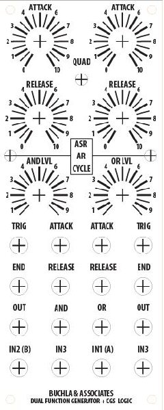
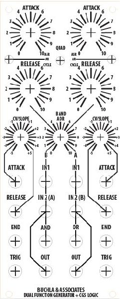
You can say that again! Here is the 5th(and better be final  ) version of my panel. Compromises are the Attack/Release CV/Slope for each function are controlled by the same dual gang pot, and the amount of function A into the And + function B into the OR share a dual gang pot as well. I'd still like to be able to switch off one of the attenuators for each function, should I ever not want both the attack and release CV attenuated the same amount, but I don't have room for any more switches. Does anyone know where I can get a 16mm body, 1/4" smooth shaft dual gang center-detent pot with push-pull SPDT switch? ) version of my panel. Compromises are the Attack/Release CV/Slope for each function are controlled by the same dual gang pot, and the amount of function A into the And + function B into the OR share a dual gang pot as well. I'd still like to be able to switch off one of the attenuators for each function, should I ever not want both the attack and release CV attenuated the same amount, but I don't have room for any more switches. Does anyone know where I can get a 16mm body, 1/4" smooth shaft dual gang center-detent pot with push-pull SPDT switch? 
God, this thing's gonna be a nightmare to put together. 5 PCB's(including LED drivers), attenuverters on a perfboard, 8 switching sockets etc... but it'll be worth it |
I like the idea, but I think your going to have to break down and go to a 3U panel...it's getting crowded in there!
clickmrmike |
|
|
Back to top
|
|
|
BananaPlug
Joined: Jul 04, 2007
Posts: 307
Location: Philly
Audio files: 5
|
| Posted: Mon Apr 07, 2008 10:13 am Post subject:
|
|
|
| Neandrewthal, maybe the thing to do is build the Analog Logic as a separate panel. More flexible that way too. |
|
|
Back to top
|
|
|
/mr
Joined: Aug 05, 2007
Posts: 223
Location: Elektron City, Sweden
Audio files: 1
|
| Posted: Mon Apr 07, 2008 10:15 am Post subject:
|
|
|
| clickmrmike wrote: | | neandrewthal wrote: | | God, this thing's gonna be a nightmare to put together. 5 PCB's(including LED drivers), attenuverters on a perfboard, 8 switching sockets etc... but it'll be worth it |
I like the idea, but I think your going to have to break down and go to a 3U panel...it's getting crowded in there! |
Definitely... and it's still just a dual Function Generator. The original b281 is a quad! |
|
|
Back to top
|
|
|
neandrewthal
Joined: May 11, 2007
Posts: 672
Location: Canada
|
| Posted: Mon Apr 07, 2008 12:05 pm Post subject:
|
|
|
| clickmrmike wrote: | | I like the idea, but I think your going to have to break down and go to a 3U panel...it's getting crowded in there! |
You can try all you want but I can never listen to reason If it's too crowded I'll probably leave of the attenuverter circuitry. Actually, 2U is the maximum size I can make myself, so I just do those since I'm a cheapskate. I'm obviously gonna have to take a hit on the Klee and MFOS sequencer though.
| BananaPlug wrote: | | Neandrewthal, maybe the thing to do is build the Analog Logic as a separate panel. More flexible that way too. |
I would, but I have this obsession with filling every square inch of panel space. Just a quirk I guess. I cannot stand to see one empty space that could hold another pot or jack. Also, the way I have it set up, you can still use the analog logic separately. You just have to turn down the hardwired attenuated EGs, then patching in the external inputs will override the unattenuated EGs.
_________________
" I went through quite a few trannies til I found one I liked" - Wild Zebra |
|
|
Back to top
|
|
|
BananaPlug
Joined: Jul 04, 2007
Posts: 307
Location: Philly
Audio files: 5
|
| Posted: Mon Apr 07, 2008 1:14 pm Post subject:
|
|
|
I'm with you in terms of not wasting panel space (raise a glass to Serge Tcherepnin). I think I made myself a little unwelcome on the Modcan Yahoo group for criticizing some of Bruce's decisions with respect to panel real estate.
I've found these to be good ways of getting a layout unstuck. In the spirit of Eno's Oblique Strategies use one of these to upset your thinking and then jiggle things around until it makes sense again:
Swap horizontal for vertical.
Use a different grouping paradigm.
Add or subtract a multiple (e.g. single, dual, triple, quad...).
Add or subtract features.
Pair it up with something relevant (e.g. your idea of the CGS A-Logic)
As a last resort, if you have leftover space for three holes add an independent voltage scaler: in, knob, out. You can build this on a scrap of perf board about the size of a postage stamp and a attach it behind the pot. |
|
|
Back to top
|
|
|
mosc
Site Admin

Joined: Jan 31, 2003
Posts: 18235
Location: Durham, NC
Audio files: 222
G2 patch files: 60
|
| Posted: Mon Apr 07, 2008 1:46 pm Post subject:
|
|
|
When I was building stuff a long time ago, I would put in unconnected jacks where there was extra space and label them "exceptions".
_________________
--Howard
my music and other stuff |
|
|
Back to top
|
|
|
Peake
Joined: Jun 29, 2007
Posts: 1113
Location: Loss Angeles
Audio files: 3
|
| Posted: Mon Apr 07, 2008 2:07 pm Post subject:
|
|
|
Technosaurus fill every space in their patchbays with jacks, and those that are unused in the module itself are linked as multiples.
"Source of Exception"?
Last edited by Peake on Mon Apr 07, 2008 8:25 pm; edited 1 time in total |
|
|
Back to top
|
|
|
neandrewthal
Joined: May 11, 2007
Posts: 672
Location: Canada
|
|
|
Back to top
|
|
|
clickmrmike
Joined: Jun 08, 2007
Posts: 48
Location: Gnashville
Audio files: 1
|
| Posted: Mon Apr 07, 2008 7:27 pm Post subject:
|
|
|
| neandrewthal wrote: | | clickmrmike wrote: | | I like the idea, but I think your going to have to break down and go to a 3U panel...it's getting crowded in there! |
You can try all you want but I can never listen to reason If it's too crowded I'll probably leave of the attenuverter circuitry. Actually, 2U is the maximum size I can make myself, so I just do those since I'm a cheapskate. I'm obviously gonna have to take a hit on the Klee and MFOS sequencer though. |
Why the 2U limitation? Are you fabbing your own metal, or using pre-painted blanks? Commercial blank MOTM-format panels are available in sizes up to 4U. I'm trying to go larger, but the paint is hard to match...I'd like to do my Klee at home, too. PM me if you want to exchange fabrication ideas.
clickmrmike |
|
|
Back to top
|
|
|
Sound
Joined: Jun 06, 2006
Posts: 842
Audio files: 1
|
| Posted: Tue Apr 08, 2008 10:58 am Post subject:
|
|
|
| /mr wrote: |
I'll try!
Do you know what a swiching jack is? The type of jack that can have an internal "preset signal" connected to it if no plug is inserted in the jack. The Korg MS-20 has lots of them, for example.
Let the Attack/Decay CV inputs have switching jacks. Connect the 281 output signal internally to these jacks. Add an "attenuverting" knob to each CV input jack - which means the knob should scale the CV by a factor of anything between -1x and 1x.
Then, if no plug is inserted in the Attack/Decay CV input jacks, they will get the feedbacked output signal and their knobs will function as continuous slope controls fading between logarithmic-linear-exponential shapes. Like Peake's suggestion above.
(But if a usual CV signal is patched in, the slope will be linear.) |
Ah! This is the behaviour of my very nice Bananalogue VCS modules. When their CV inputs are unplugged the CVattenuators work as continuous slope controls fading between logarithmic-linear-exponential shapes.
But they make it in another way because I don't see any swithching jacks.
But is it so easy? Only connect the output to the CV input?
| /mr wrote: |
Yes!!! I know, it's weird - but yes! If you want true control of them.
BUT: I'd love to see somebody make a rough calculation of a typical mid-sized modular system with lots of nice (but often pot-less) CV jacks and the number of external attenuators needed, and then count all the associated hardware needed for this. Skip the pots and knobs, but count the extra jacks - two at each knob - and the extra cables - one for each external knob in use. In case of attenuverters, count the components behind the panel - the PCBs, the electronics, the power connection. The extra power connectors needed in the main PSU distribution.
I get the feeling that this amount of hardware is getting comparable to the knobs that was eliminated in the first place. And the extra jacks take up panel space. And the knobs for CV Sensitivity end up off-module. And... even worse... clever bonus features like the "switched-jack connected slope control" above can definitely be forgotten! |
I think you are right... It have sense. Also it's more fast and intuitive to have the attenuator close the CV input... I'll think more about that! |
|
|
Back to top
|
|
|
toppobrillo
Joined: Dec 10, 2005
Posts: 766
Location: oakland, ca
G2 patch files: 1
|
| Posted: Tue Apr 08, 2008 1:28 pm Post subject:
|
|
|
| Quote: | | But they make it in another way because I don't see any swithching jacks. |
doesn't it have pull-switch pots?
| Quote: | | But is it so easy? |
basically, yes. |
|
|
Back to top
|
|
|
|

 Forum index » DIY Hardware and Software