| Author |
Message |
funkyfarm

Joined: Jan 21, 2007
Posts: 583
Location: France
Audio files: 3
|
|
|
Back to top
|
|
 |
guitarfool

Joined: Feb 26, 2007
Posts: 162
Location: Maryland
Audio files: 8
|
 Posted: Fri May 02, 2008 8:28 pm Post subject: Posted: Fri May 02, 2008 8:28 pm Post subject:
|
  |
|
According to Mouser (they have both parts), the first one is made by Texas Instruments, the second by STMicroelectronics. Both are PDIP-8. At first glance, both spec sheets seem to have the same values for everything.
Oh, at Mouser, The TI part costs 1 cent more  |
|
|
Back to top
|
|
|
/mr
Joined: Aug 05, 2007
Posts: 223
Location: Elektron City, Sweden
Audio files: 1
|
| Posted: Sat May 03, 2008 1:26 am Post subject:
|
|
|
| funkyfarm wrote: | Are the two letters after "OP-07" are important for a FS1a application ?
OP-07 CP : €0.36 @banzaieffects
OP-07CN :€1.45 @ farnell ?!
First, I guess i could use the 0,36€ version |
Yes, do it. 
It's just the first character C that matters, I think the P or N is just different ways of saying that it's a plastic DIP package.
There's also a D version with almost equally good specifications. I suspect this to perform well enough too, since the differences are really tiny. |
|
|
Back to top
|
|
|
jhaible
Joined: May 25, 2007
Posts: 2014
Location: Germany
Audio files: 24
|
| Posted: Sat May 03, 2008 3:21 am Post subject:
Re: Frequency Shifter |
|
|
| fredw wrote: | | would be great! |
I still have some left - email me.
JH.
_________________
"I tell you the truth, if anyone says to this mountain, 'Go, throw yourself into the sea,' and does not doubt in his heart but believes that what he says will happen, it will be done for him. Therefore I tell you, whatever you ask for in prayer, believe that you have received it, and it will be yours." (Mk 11,23f) |
|
|
Back to top
|
|
|
jhaible
Joined: May 25, 2007
Posts: 2014
Location: Germany
Audio files: 24
|
| Posted: Sat May 03, 2008 3:27 am Post subject:
|
|
|
OP-07:
I expect every version of this chip to fit in here. It's a very common part - that's why I used it in the first place. (The important parameters here were: low offset, slow and well-natured response.)
I just checked what brand I have in my prototypes: it's the TI parts, OP07CP.
JH.
_________________
"I tell you the truth, if anyone says to this mountain, 'Go, throw yourself into the sea,' and does not doubt in his heart but believes that what he says will happen, it will be done for him. Therefore I tell you, whatever you ask for in prayer, believe that you have received it, and it will be yours." (Mk 11,23f) |
|
|
Back to top
|
|
|
/mr
Joined: Aug 05, 2007
Posts: 223
Location: Elektron City, Sweden
Audio files: 1
|
| Posted: Sat May 03, 2008 3:49 am Post subject:
|
|
|
Good to know.
What about the TL07x chips? Their Vio differ between versions:
"B" (best), "A" (medium), " " (worst).
I have some different chips, would be nice to put the best ones in the right places - if it matters at all. |
|
|
Back to top
|
|
|
jhaible
Joined: May 25, 2007
Posts: 2014
Location: Germany
Audio files: 24
|
| Posted: Sat May 03, 2008 4:36 am Post subject:
|
|
|
| /mr wrote: | Good to know.
What about the TL07x chips? Their Vio differ between versions:
"B" (best), "A" (medium), " " (worst).
I have some different chips, would be nice to put the best ones in the right places - if it matters at all. |
Where I specified TL07x, offset is not an issue - so you can use the cheapest version.
JH.
_________________
"I tell you the truth, if anyone says to this mountain, 'Go, throw yourself into the sea,' and does not doubt in his heart but believes that what he says will happen, it will be done for him. Therefore I tell you, whatever you ask for in prayer, believe that you have received it, and it will be yours." (Mk 11,23f) |
|
|
Back to top
|
|
|
jhaible
Joined: May 25, 2007
Posts: 2014
Location: Germany
Audio files: 24
|
| Posted: Tue May 20, 2008 3:03 pm Post subject:
|
|
|
Just being curious - has anybody finished building his Frequency Shifter yet?
JH.
_________________
"I tell you the truth, if anyone says to this mountain, 'Go, throw yourself into the sea,' and does not doubt in his heart but believes that what he says will happen, it will be done for him. Therefore I tell you, whatever you ask for in prayer, believe that you have received it, and it will be yours." (Mk 11,23f) |
|
|
Back to top
|
|
|
toppobrillo

Joined: Dec 10, 2005
Posts: 766
Location: oakland, ca
G2 patch files: 1
|
| Posted: Wed May 21, 2008 4:47 pm Post subject:
|
|
|
not yet, scrounging around for parts.. looks like i'm going to have to place an order..
been working on panel designs lately- which i have not yet finalized, by the way. anybody else done a panel? |
|
|
Back to top
|
|
|
guitarfool
Joined: Feb 26, 2007
Posts: 162
Location: Maryland
Audio files: 8
|
| Posted: Wed May 21, 2008 8:10 pm Post subject:
|
|
|
| topp wrote: | | anybody else done a panel? |
I'm still struggling with it, along with my panel layout for the Klee, String Filter, and Buchla 281 EG 
I've got silkscreens on the way for 9 other panels (including the solina chorus), so I'll also be printing up panels this weekend. I'd like to get all my building done before my eyesight is gone, and have enough time to play with it all before my hearing goes 
But I have starting stuffing the Frequency Shifter boards. Since I'm using +/-15V dotcom power, I can leave out U1, U2, D1-D5, C1-C6 and R1-R6 on board 2, right? |
|
|
Back to top
|
|
|
jhaible
Joined: May 25, 2007
Posts: 2014
Location: Germany
Audio files: 24
|
| Posted: Thu May 22, 2008 2:13 am Post subject:
|
|
|
| guitarfool wrote: | | topp wrote: | | anybody else done a panel? |
I'm still struggling with it, along with my panel layout for the Klee, String Filter, and Buchla 281 EG
I've got silkscreens on the way for 9 other panels (including the solina chorus), so I'll also be printing up panels this weekend. I'd like to get all my building done before my eyesight is gone, and have enough time to play with it all before my hearing goes
But I have starting stuffing the Frequency Shifter boards. Since I'm using +/-15V dotcom power, I can leave out U1, U2, D1-D5, C1-C6 and R1-R6 on board 2, right? |
Yes, omit the obvious power supply parts.
And make sure you have a *short* connection to your power supply.
The on-board compander helps to get rid of oscillator bleedthru, and does this quite nicely when everything is well adjusted. But if anything comes in _after_ the compander, coupled by a long GND connection to the PSU, the compander cannot suppress that.
We're talking about rather low bleedthru levels here, and it doesn't matter much when you have large audio signals - but if you have the choice, better plan to place the FS-1a close to the power supply.
Also, when using the on-board PSY, position the two boards such that the sides with the +0- connector (+/-15V) are facing each other, to keep that connection short.
JH.
_________________
"I tell you the truth, if anyone says to this mountain, 'Go, throw yourself into the sea,' and does not doubt in his heart but believes that what he says will happen, it will be done for him. Therefore I tell you, whatever you ask for in prayer, believe that you have received it, and it will be yours." (Mk 11,23f) |
|
|
Back to top
|
|
|
neandrewthal
Joined: May 11, 2007
Posts: 672
Location: Canada
|
| Posted: Thu May 22, 2008 9:13 am Post subject:
|
|
|
Uh-oh. What if it is not possible to even put it in the same cabinet as the power supply. Would the bleedthrough be unbearable?
_________________
" I went through quite a few trannies til I found one I liked" - Wild Zebra |
|
|
Back to top
|
|
|
paologatto
Joined: Apr 25, 2007
Posts: 9
Location: bologna
Audio files: 2
|
| Posted: Thu May 22, 2008 9:54 am Post subject:
|
|
|
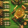
I finished to buid it some days ago.. here is a picture:

The adjustment procedure was simple and all went as you described.
But I noticed 2 things that make me think that I made some mistakes in the building:
- also when the dry-wet pots are set all to dry in the output the signal is low-pass filtered. Is this by design?
- there is a sort of sublte feedback at the frequency of the oscillator: when a signal in input is stopped there is an oscillation that shortly ends. Is also this normal?
On the use of the frequency shifter I still have to learn. It's a very complicate machine indeed! Currently I don't have external CV source, here is an example of use just moving the frequency controls. Some notes played through the frequency shifter and the same recorded directly from the synth (an A6 Andromeda).
| Description: |
|

Download (listen) |
| Filename: |
fs-alldry.mp3 |
| Filesize: |
3.61 MB |
| Downloaded: |
798 Time(s) |
| Description: |
|
Download (listen) |
| Filename: |
fs-90wet.mp3 |
| Filesize: |
3.63 MB |
| Downloaded: |
827 Time(s) |
|
|
|
Back to top
|
|
|
jhaible
Joined: May 25, 2007
Posts: 2014
Location: Germany
Audio files: 24
|
| Posted: Thu May 22, 2008 11:12 am Post subject:
|
|
|
| neandrewthal wrote: | | Uh-oh. What if it is not possible to even put it in the same cabinet as the power supply. Would the bleedthrough be unbearable? |
I don't know how bad it will be.
But there's an easy cure: spend 10 dollars for a transformer and fuses.
The PSU is on the board already!
JH.
_________________
"I tell you the truth, if anyone says to this mountain, 'Go, throw yourself into the sea,' and does not doubt in his heart but believes that what he says will happen, it will be done for him. Therefore I tell you, whatever you ask for in prayer, believe that you have received it, and it will be yours." (Mk 11,23f) |
|
|
Back to top
|
|
|
jhaible
Joined: May 25, 2007
Posts: 2014
Location: Germany
Audio files: 24
|
| Posted: Thu May 22, 2008 11:31 am Post subject:
|
|
|
| paologatto wrote: |
- also when the dry-wet pots are set all to dry in the output the signal is low-pass filtered. Is this by design?
|
No. First thing to check: The small capacitors that are in the feedback of the opamps. They should only roll off the frequency response _above_ the audio range - not do any serious low pass filtering.
Double check if they have the requred value. Example: 33pF
There are ceramics marked "330" that have 33pF (33 * 10^0), and some where 330 reads as 330pF.
| Quote: |
- there is a sort of sublte feedback at the frequency of the oscillator: when a signal in input is stopped there is an oscillation that shortly ends. Is also this normal? |
Sounds like remaining bleedthru from the oscillator. This should be quite small even *before* the compander closes down (that's what you hear ending, when it's suppressed). With the specified resistor values, the compander has a very slow release tail. You can speed this up by decreasing R147 (near U21 on PCB 1) from 4.7M to something smaller. Connect a 1M or 470k in parallel with R147.
You can even connect a 5Meg audio taper pot + 100k series resistor in parallel with R147 to have an adjustable release time.
| Quote: | | On the use of the frequency shifter I still have to learn. It's a very complicate machine indeed! Currently I don't have external CV source, here is an example of use just moving the frequency controls. Some notes played through the frequency shifter and the same recorded directly from the synth (an A6 Andromeda). |
For first experiments, I recommend this:
Mix fully on wet. Modulation frequency a couple 100 Hz.
Play percussive notes thru this. (piano or clavinet-like tones)
Try upshift and downshift.
Listen to it in stereo with both outputs in upshift, then switch *one* to downshift while playing on.
JH.
_________________
"I tell you the truth, if anyone says to this mountain, 'Go, throw yourself into the sea,' and does not doubt in his heart but believes that what he says will happen, it will be done for him. Therefore I tell you, whatever you ask for in prayer, believe that you have received it, and it will be yours." (Mk 11,23f) |
|
|
Back to top
|
|
|
paologatto
Joined: Apr 25, 2007
Posts: 9
Location: bologna
Audio files: 2
|
| Posted: Thu May 22, 2008 12:25 pm Post subject:
|
|
|
| jhaible wrote: | | paologatto wrote: |
- also when the dry-wet pots are set all to dry in the output the signal is low-pass filtered. Is this by design?
|
No. First thing to check: The small capacitors that are in the feedback of the opamps. They should only roll off the frequency response _above_ the audio range - not do any serious low pass filtering.
Double check if they have the requred value. Example: 33pF
There are ceramics marked "330" that have 33pF (33 * 10^0), and some where 330 reads as 330pF.
| Quote: |
- there is a sort of sublte feedback at the frequency of the oscillator: when a signal in input is stopped there is an oscillation that shortly ends. Is also this normal? |
Sounds like remaining bleedthru from the oscillator. This should be quite small even *before* the compander closes down (that's what you hear ending, when it's suppressed). With the specified resistor values, the compander has a very slow release tail. You can speed this up by decreasing R147 (near U21 on PCB 1) from 4.7M to something smaller. Connect a 1M or 470k in parallel with R147.
You can even connect a 5Meg audio taper pot + 100k series resistor in parallel with R147 to have an adjustable release time.
| Quote: | | On the use of the frequency shifter I still have to learn. It's a very complicate machine indeed! Currently I don't have external CV source, here is an example of use just moving the frequency controls. Some notes played through the frequency shifter and the same recorded directly from the synth (an A6 Andromeda). |
For first experiments, I recommend this:
Mix fully on wet. Modulation frequency a couple 100 Hz.
Play percussive notes thru this. (piano or clavinet-like tones)
Try upshift and downshift.
Listen to it in stereo with both outputs in upshift, then switch *one* to downshift while playing on.
JH. |
Thank you for the help Jurgen! As soon as I finish the "Jurgen Box" I'll check what's wrong with the frequency shifter..
BTW all your other 3 effects I've built work and sound perfectly!
PS: here is a preview of the Jurgen Box, when finished I'll post some more pictures
 |
|
|
Back to top
|
|
|
/mr
Joined: Aug 05, 2007
Posts: 223
Location: Elektron City, Sweden
Audio files: 1
|
|
|
Back to top
|
|
|
mosc
Site Admin

Joined: Jan 31, 2003
Posts: 18319
Location: Durham, NC
Audio files: 235
G2 patch files: 60
|
| Posted: Fri May 23, 2008 10:55 am Post subject:
|
|
|
| paologatto wrote: |
PS: here is a preview of the Jurgen Box, when finished I'll post some more pictures
|
Please don't include any more links to imageshack.us because there are ugly pop up ads. If you want to share photos, please just post them here as an attachment. Your photos are good, it's just that site that's ugly.
Thanks.
_________________
--Howard
my music and other stuff |
|
|
Back to top
|
|
|
toppobrillo
Joined: Dec 10, 2005
Posts: 766
Location: oakland, ca
G2 patch files: 1
|
| Posted: Fri May 23, 2008 4:17 pm Post subject:
|
|
|
| Quote: | The last one who finishes it will have to pay for the other ones... Wink
|
what a great motivator to finish projects! i'd like to try that sometime!
i really still can't decide whether to put this in it's own 2U rack or try a 4U x say 6" panel. i think i'd like to bring the VCO outputs out to the front and also perhaps the dome filter out too. i am really excited at the fact that this filter covers such a wide range- seems like it could be useful on it's own as well. |
|
|
Back to top
|
|
|
synth_ollie

Joined: Sep 11, 2006
Posts: 149
Location: sweden
|
| Posted: Sat May 31, 2008 12:30 am Post subject:
|
|
|
| topp wrote: | | Quote: | The last one who finishes it will have to pay for the other ones... Wink
|
what a great motivator to finish projects! i'd like to try that sometime!
|
well, that will propably be me then, havent had time to even take a closer look at the boards yet... |
|
|
Back to top
|
|
|
/mr
Joined: Aug 05, 2007
Posts: 223
Location: Elektron City, Sweden
Audio files: 1
|
| Posted: Wed Jun 18, 2008 6:34 am Post subject:
Decoupling caps, different methods |
|
|
I notice that supply decoupling caps are placed between (+) and (-) supplies instead of the perhaps more common supply-to-ground.
Can you give a good short explanation of the pros and cons in different situations? |
|
|
Back to top
|
|
|
jhaible
Joined: May 25, 2007
Posts: 2014
Location: Germany
Audio files: 24
|
| Posted: Wed Jun 18, 2008 11:16 am Post subject:
Re: Decoupling caps, different methods |
|
|
| /mr wrote: | I notice that supply decoupling caps are placed between (+) and (-) supplies instead of the perhaps more common supply-to-ground.
Can you give a good short explanation of the pros and cons in different situations? |
Oh, how do you call this in English - opening a can of worms ? 
There are different philosophies for placing decoupling caps, and there are different goals to achieve.
One possible goal is to keep the supply noise low, even when an opamp is driving rather heavy loads. In that case, you have to follow your load current with your decoupling caps: If the opamp drives low impedance to GND, you need to decouple the + and - supply rails to GND; and not to just any GND point either, but to the point where your load is grounded.
If you have one opamp driving the virtual GND node of a second, inverting, amplifier via a small resistance, you'd have to decouple the positive supply of the first opamp to the negative supply of the second opamp, and vice versa. Just closing the current loop with a part as short as possible with capacitors.
IMO, this (last paragraph) is an exotic case, however. Important for power amplifiers with ultro low distortion, most likely.
For all my low-current audio opamp circuits, there is just a single design goal for the bypass caps: Make the circuit stable. Prevent it from ringing. Staying clear from self oscillation. And here, in most cases, decoupling +vb to -vb does the job.
I got this advice from a TI opamp specialist (former Burr Brown specialist): Decouple +vcc to -vee on every opamp, and just make sure there are a _few_ extra caps from -vee to GND, spread over the board.
I do it that way ever since, and never had oscillation problems.
JH.
_________________
"I tell you the truth, if anyone says to this mountain, 'Go, throw yourself into the sea,' and does not doubt in his heart but believes that what he says will happen, it will be done for him. Therefore I tell you, whatever you ask for in prayer, believe that you have received it, and it will be yours." (Mk 11,23f) |
|
|
Back to top
|
|
|
Fetafarmer
Joined: Jul 29, 2007
Posts: 32
|
| Posted: Wed Jun 18, 2008 11:19 am Post subject:
|
|
|
Hi Jürgen,
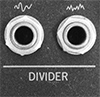
I was considering using a 10-turn pot for linear control from the panel (leaving the Fine pot away). Is the purpose of the LEDs at DirLD to provide orientation within the linear frequency range in such a configuration?
thanks!
kevin |
|
|
Back to top
|
|
|
jhaible
Joined: May 25, 2007
Posts: 2014
Location: Germany
Audio files: 24
|
| Posted: Wed Jun 18, 2008 11:29 am Post subject:
|
|
|
| Fetafarmer wrote: | Hi Jürgen,
I was considering using a 10-turn pot for linear control from the panel (leaving the Fine pot away). Is the purpose of the LEDs at DirLD to provide orientation within the linear frequency range in such a configuration?
thanks!
kevin |
Yes, this will work, and yes, the Dir Led will be helpful in th eway you describe it.
JH.
_________________
"I tell you the truth, if anyone says to this mountain, 'Go, throw yourself into the sea,' and does not doubt in his heart but believes that what he says will happen, it will be done for him. Therefore I tell you, whatever you ask for in prayer, believe that you have received it, and it will be yours." (Mk 11,23f) |
|
|
Back to top
|
|
|
mosc
Site Admin
Joined: Jan 31, 2003
Posts: 18319
Location: Durham, NC
Audio files: 235
G2 patch files: 60
|
| Posted: Wed Jun 18, 2008 1:02 pm Post subject:
Re: Decoupling caps, different methods |
|
|
| jhaible wrote: |
One possible goal is to keep the supply noise low, even when an opamp is driving rather heavy loads. In that case, you have to follow your load current with your decoupling caps: If the opamp drives low impedance to GND, you need to decouple the + and - supply rails to GND; and not to just any GND point either, but to the point where your load is grounded.
If you have one opamp driving the virtual GND node of a second, inverting, amplifier via a small resistance, you'd have to decouple the positive supply of the first opamp to the negative supply of the second opamp, and vice versa. Just closing the current loop with a part as short as possible with capacitors.
IMO, this (last paragraph) is an exotic case, however. Important for power amplifiers with ultro low distortion, most likely.
For all my low-current audio opamp circuits, there is just a single design goal for the bypass caps: Make the circuit stable. Prevent it from ringing. Staying clear from self oscillation. And here, in most cases, decoupling +vb to -vb does the job.
I got this advice from a TI opamp specialist (former Burr Brown specialist): Decouple +vcc to -vee on every opamp, and just make sure there are a _few_ extra caps from -vee to GND, spread over the board.
I do it that way ever since, and never had oscillation problems. |
I have been building circuits for years. Every good designer I've spoken to has different rules of thumb. It's not an exact science, but closer to a craft or art. This practice seems very sound to me. My suggestion to everyone is pick a methodology and stick to it rigorously. Then, down the road, if you have some problems the time you spend correcting them will be not just to improve a particular circuit or layout, but to improve your method.
_________________
--Howard
my music and other stuff |
|
|
Back to top
|
|
|
|

 Forum index » DIY Hardware and Software » Jürgen Haible designs


