| Author |
Message |
Sound
Joined: Jun 06, 2006
Posts: 842
Audio files: 1
|
 Posted: Thu Dec 18, 2008 4:56 am Post subject: Posted: Thu Dec 18, 2008 4:56 am Post subject:
|
  |
|
| helitron wrote: | same here, ...no idea why. I just found it out by chance while testing the VC functions using a joystic as voltage source.
however I still have no clue what the trimmpot is good for. I tried what sound wrote, but I couldnt get both outputs at the same level (6.4V). |
I mean peak to peak. In the output is 0V to 6.4V, and in the AC output was anything like, -4V to + 2.4. |
|
|
Back to top
|
|
 |
TekniK

Joined: Aug 10, 2008
Posts: 1059
|
| Posted: Fri Dec 19, 2008 2:17 am Post subject:
|
|
|
| zthee wrote: | But from what I heard the guy who owns the rights to build Serge modules keeps everything on a tight leash? But I mean why are there practicly no Serge schematics online?
The schematics for the Serge VCS and a real CGS (2" x 6") board would be great though!  |
You have all the schematics now!
Last edited by TekniK on Thu Aug 19, 2010 3:37 am; edited 1 time in total |
|
|
Back to top
|
|
|
Luka

Joined: Jun 29, 2007
Posts: 1003
Location: Melb.
|
|
|
Back to top
|
|
|
zthee

Joined: Feb 20, 2008
Posts: 414
Location: Stockholm
|
| Posted: Mon Dec 29, 2008 12:31 pm Post subject:
|
|
|
| sduck wrote: | | Here's the pcb in motm format - |
Just realized - that your pcb has a bipolar out area. Something I don't have on my eurorack pcbs..
Though it's just a TL071 and a few other parts.. so I guess it's doable! |
|
|
Back to top
|
|
|
sduck

Joined: Dec 16, 2007
Posts: 459
Location: Nashville
Audio files: 5
|
| Posted: Sun Feb 08, 2009 9:01 pm Post subject:
|
|
|
So I just finished up building this motm format version. Seems to work ok - all the pots and jacks do things, although I'm not familiar enough with the thing to know for sure if they're doing the right things.
The led doesn't work. And I was getting this weird behavior on the fall of the slope where it would dip below zero and then rise back to zero. Upon staring at the pcb enough it looked like the led wires might be labeled backwards, so I switched the wires. The led still doesn't work (I checked the led - it's functional), but the weird end of cycle behavior is gone. So perhaps I just have a wrong led type.
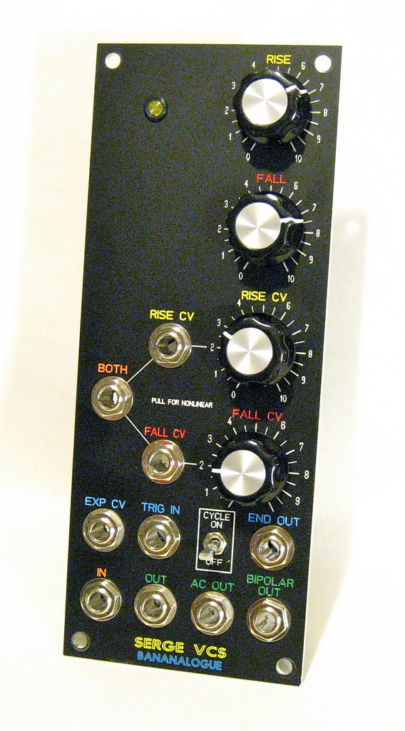
Fun unit - I hooked up all the patches as described on the old bananalogue page to test it, and they all work as described. The knobs are really touchy - there's some pretty big range on these things.
 |
|
|
Back to top
|
|
|
andrewF

Joined: Dec 29, 2006
Posts: 1176
Location: australia
Audio files: 4
|
| Posted: Sun Feb 08, 2009 11:32 pm Post subject:
|
|
|
I haven't seen this PCB, but if all the outputs work and just the LEd doesn't, the problem can't be too hard to sort.
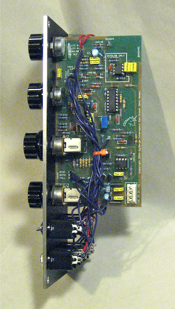
would the transistor/diode/resistor near the LED holes be a LED driver subcct?
maybe it is something like Ken's LED driver PCB

edit
just found this image on P2 of this thread

it looks like the LED A&K markings are reversed. The led's cathode 'K' should go to the 1k resistor.
Also the hole marked 'K' should not be connected to 0V, that track should be cut and a connection made to +12V
this is just guesswork from looking at the PCB and Ken's led-driver. hope this doesn't blow it up |
|
|
Back to top
|
|
|
sduck
Joined: Dec 16, 2007
Posts: 459
Location: Nashville
Audio files: 5
|
| Posted: Mon Feb 09, 2009 7:28 am Post subject:
|
|
|
| That fixed it! I had already switched the wires, so cutting the anode wire from the led and running a wire from a 15+v rail to the cut worked. 100% working now! Thanks! |
|
|
Back to top
|
|
|
creatorlars

Joined: Nov 26, 2007
Posts: 524
Location: Denton, TX
Audio files: 4
|
| Posted: Sun Apr 12, 2009 9:25 pm Post subject:
|
|
|
I can confirm that I'm having an identical problem with the rise pot not working as it should -- I've double checked all my wiring and parts, everything's correct according to the board. This is pretty frustrating, with no schematics to look at. 
Any further developments with this, or anyone have theories? What exactly did you do to fix it? The module seems to work fine otherwise. |
|
|
Back to top
|
|
|
helitron
Joined: Feb 27, 2008
Posts: 21
Location: vienna
|
| Posted: Sun Apr 12, 2009 11:36 pm Post subject:
|
|
|
| creatorlars wrote: | I can confirm that I'm having an identical problem with the rise pot not working as it should -- I've double checked all my wiring and parts, everything's correct according to the board. This is pretty frustrating, with no schematics to look at.
Any further developments with this, or anyone have theories? What exactly did you do to fix it? The module seems to work fine otherwise. |
try shorting V+ to the VC-rise socket. that helped...
hel |
|
|
Back to top
|
|
|
creatorlars
Joined: Nov 26, 2007
Posts: 524
Location: Denton, TX
Audio files: 4
|
| Posted: Sun Apr 12, 2009 11:41 pm Post subject:
|
|
|
| I will try that, but won't it make the VC Rise jack/attenuator unusable? I am using banana jacks so I can't take advantage of a switched connection. |
|
|
Back to top
|
|
|
sduck
Joined: Dec 16, 2007
Posts: 459
Location: Nashville
Audio files: 5
|
| Posted: Wed Apr 15, 2009 7:11 am Post subject:
|
|
|
| I've seen that +15v to the rise jack mentioned several times, and it sounds bogus to me. If that was the way to fix it, then you'd have a useless jack - or one with +15v hitting everything that's plugged into it. My VCS (see above) doesn't have +15v coming out of the rise jack, and it works correctly. I'm going to have to sit for a while and compare the euro pcb against my working motm pcb and see what the difference is - I'm pretty sure it's some small error in the traces. |
|
|
Back to top
|
|
|
Funky40
Joined: Sep 24, 2005
Posts: 875
Location: Swiss
Audio files: 1
G2 patch files: 5
|
| Posted: Fri Apr 17, 2009 3:31 pm Post subject:
|
|
|
| sduck wrote: | | I'm going to have to sit for a while and compare the euro pcb against my working motm pcb and see what the difference is - I'm pretty sure it's some small error in the traces. |
that would be very nice |
|
|
Back to top
|
|
|
Luka
Joined: Jun 29, 2007
Posts: 1003
Location: Melb.
|
|
|
Back to top
|
|
|
TekniK
Joined: Aug 10, 2008
Posts: 1059
|
| Posted: Sat May 30, 2009 3:11 am Post subject:
|
|
|
Okay, a demo with this VCS,with VC control of rise & fall (only one VCS in this patch)
Last edited by TekniK on Thu Aug 19, 2010 3:37 am; edited 1 time in total |
|
|
Back to top
|
|
|
pristak
Joined: Nov 17, 2006
Posts: 37
Location: Dallas, Texas
|
| Posted: Sun May 31, 2009 7:04 am Post subject:
|
|
|
| I just finished one of mine last night. Mine are the MOTM single board version. It was 2am so I need to put it through it's paces today once the family wakes up but I confirmed it did some of what it is supposed to do last night. |
|
|
Back to top
|
|
|
koura
Joined: Feb 02, 2009
Posts: 13
Location: chicago
|
| Posted: Fri Jun 19, 2009 6:35 am Post subject:
|
|
|
| unit-sound wrote: | >> I shorted V+ to the VC-rise socket
jan |
Any update on this fix?
About to finish building a board a got and wanted to see how this has worked out. To be 100% clear you are shorting V+ to the VC-rise input which is a switched jack? If its not a switched jack I would assume this couldn't work as you would constantly have V+ going through regardless of the input.
thanks for any info as i know this is an old thread by now |
|
|
Back to top
|
|
|
TekniK
Joined: Aug 10, 2008
Posts: 1059
|
| Posted: Fri Jun 19, 2009 12:15 pm Post subject:
|
|
|
The board where sold to us with an error,and those asses did know it very well,now u know why no support was given!,bastards.
just do this 'debug' and it will work like it should be: |
|
|
Back to top
|
|
|
e-grad
Joined: Sep 12, 2008
Posts: 142
Location: Berlin
|
| Posted: Fri Jun 19, 2009 2:50 pm Post subject:
|
|
|
| Thanks for sharing! |
|
|
Back to top
|
|
|
janvanvolt

Joined: Nov 24, 2005
Posts: 285
Location: Mainz, Germany
|
| Posted: Mon Oct 12, 2009 6:52 pm Post subject:
|
|
|
I still have issues (after having +/- 15V reversed at one time). Nothing seems to work
Exchanged already are all IC's and Transistors.
The "kludge" has also been applied.
Any ideas on how to debug this lovely VCS ? It's sad it does nothing.
_________________
Homepage - http://www.czmok.de
My dIY - http://diy.czmok.de
Film/Music - http://gfm.me |
|
|
Back to top
|
|
|
TekniK
Joined: Aug 10, 2008
Posts: 1059
|
| Posted: Mon Oct 12, 2009 11:38 pm Post subject:
|
|
|
| should work,re-check your wiring ,soldering and components |
|
|
Back to top
|
|
|
janvanvolt
Joined: Nov 24, 2005
Posts: 285
Location: Mainz, Germany
|
|
|
Back to top
|
|
|
TekniK
Joined: Aug 10, 2008
Posts: 1059
|
| Posted: Tue Oct 13, 2009 5:02 am Post subject:
|
|
|
| unit-sound wrote: | | I've got one the "original" boards from Bananalogue, so this is a bit different from the CGS version... |
am not talking abouth the CGS version either. |
|
|
Back to top
|
|
|
fadeddata
Joined: Dec 27, 2004
Posts: 43
Location: Nashville TN
|
|
|
Back to top
|
|
|
janvanvolt
Joined: Nov 24, 2005
Posts: 285
Location: Mainz, Germany
|
|
|
Back to top
|
|
|
TekniK
Joined: Aug 10, 2008
Posts: 1059
|
| Posted: Wed Oct 14, 2009 3:28 am Post subject:
|
|
|
| unit-sound wrote: | | Okay, got it sorted out. It was the Inter-PCB wiring as well as two defective 2N's |
Like i told  |
|
|
Back to top
|
|
|
|

 Forum index » DIY Hardware and Software


