| Author |
Message |
elmegil

Joined: Mar 20, 2012
Posts: 2179
Location: Chicago
Audio files: 16
|
 Posted: Wed Aug 14, 2013 7:32 am Post subject: Posted: Wed Aug 14, 2013 7:32 am Post subject:
|
  |
|
xpmtl:
How hard is the SMT built? I have done one tiny bit of SMT soldering, a bunch of 1206 (I think?) bypass caps on a wogglebug.
I like the idea of 1U MOTM, since that's the format I use, but I'm a bit intimidated by all the tiny things in yours  . . |
|
|
Back to top
|
|
 |
THeff

Joined: Sep 01, 2006
Posts: 229
Location: Florida
Audio files: 33
|
| Posted: Wed Aug 14, 2013 10:27 am Post subject:
|
|
|
Hi elmegil,
I built xpmtl's SMD board and it went together very easy and worked the first time I tried it.
I would recommend three things:
1.) Liquid solder flux for the IC's, they will solder much easier. It doesn't take much, just a little dab on each IC pad.
2.) A good set of tweezers, cheap ones will shoot the part across the room if you are not careful.
3.) A magnifying head lens (depending on your age  ) )
If your budget allows, a hot air solder/desoldering machine is really helpful for parts that have more than two leads.
I don't own this model but it will probably work fine. http://www.circuitspecialists.com/i-182127.html
Regards,
Theff |
|
|
Back to top
|
|
|
elmegil
Joined: Mar 20, 2012
Posts: 2179
Location: Chicago
Audio files: 16
|
| Posted: Wed Aug 14, 2013 10:58 am Post subject:
|
|
|
Thanks THeff
I have the good tweezers (though I'm not sure offhand where in the mess that is my desk that they have wandered to) and I bought syringes (?) of liquid flux and I think solder too, along with a few schmartboards, because I accidentally bought the SMT version of the CA3140 a little bit back But I haven't actually used them yet.
I appreciate the advice. |
|
|
Back to top
|
|
|
jmejia
Joined: Mar 12, 2009
Posts: 114
Location: portland
|
| Posted: Wed Aug 14, 2013 10:59 am Post subject:
|
|
|
| mono-poly wrote: | | xpmtl wrote: | I think jmejia is doing an universal board that will work for all formats, an I think he will sell those.
Mine is 1U MOTM format, but i won't sell them. All the info and gerbers files are free to download on my site (sdiy.xpmtl.net). You'll have to send the gerbers to a fab house and source/populate the boards yourself.
Cheers,
x. |
Woow great work!
Looking forward to your gerber files! |
We'll also be publishing gerbers of our through-hole layout if you prefer (and aren't in a hurry) Still waiting on some replacement parts before we can do the final testing of the layout - but it's def. top priority on the bench right now. |
|
|
Back to top
|
|
|
xpmtl

Joined: Aug 10, 2007
Posts: 162
Location: Brussels, Belgium
|
| Posted: Wed Aug 21, 2013 3:21 am Post subject:
|
|
|
Well Tim responded already, building is not very difficult.
For the resistors/caps, put a small amount of solder on one pad, align the component and slide it in place as you heat the pad. Then solder the other end. For the ICs, use Flux and solder one pin first as you align the component with tweezers. After that solder the remaining pins one by one or use the sliding method ( look on Youtube, there a bunch of tutorials for soldering SMT).
I have a Hot air station but i find the results less clean than with a soldering iron. Usually components pop out of their place when i apply heat. I think my soldering paste is not very good. It's new tho (Chipquick™ water washable leaded)
As for my lack of updates lately, i had a car crash and i need to find/finance a new car so SDIY is a bit on hold... should resume mid cctober when i get back from holidays. I'll make a prototype of the frontpanel then and post the .fpd file on my site.
If anyone wants the file now i can PM it but you'll have to triple check it as it still has errors.
x.
_________________
http://sdiy.xpmtl.net |
|
|
Back to top
|
|
|
THeff
Joined: Sep 01, 2006
Posts: 229
Location: Florida
Audio files: 33
|
| Posted: Wed Aug 21, 2013 8:56 pm Post subject:
|
|
|
Wow xpmtl,
Sorry about your car man!  that stinks! that stinks!
Hope you are ok?
Hang in there...
-Tim |
|
|
Back to top
|
|
|
xpmtl
Joined: Aug 10, 2007
Posts: 162
Location: Brussels, Belgium
|
| Posted: Thu Aug 22, 2013 1:40 am Post subject:
|
|
|
Thanks Tim,
I'm fine, it was just crushed metal and a lot of paper work, waiting for the insurance company to pay back, ordering new car, etc...
I'll get the new car when i come back from holidays early october so things will settle down by then.
x.
_________________
http://sdiy.xpmtl.net |
|
|
Back to top
|
|
|
diablojoy

Joined: Sep 07, 2008
Posts: 809
Location: melbourne australia
Audio files: 11
|
| Posted: Thu Aug 22, 2013 2:13 am Post subject:
|
|
|
SMT isnt difficult at those sizes
I normally do that size with a standard iron , normal solder and little blobs of bluetack to temporarily hold things in place while i solder the other end:lol: certainly quicker than thru hole
_________________
In an infinite universe one might very well
ask where the hell am I
oh yeah thats right the land of OZ
as good an answer as any |
|
|
Back to top
|
|
|
silwerfeldt
Joined: Aug 21, 2013
Posts: 2
Location: sweden
|
| Posted: Fri Aug 23, 2013 4:03 am Post subject:
|
|
|
I just want to say thank you for all your hard work and I really look forward building my SDS 3. I´ve always wanted to tray it out...
Cheers |
|
|
Back to top
|
|
|
jmejia
Joined: Mar 12, 2009
Posts: 114
Location: portland
|
| Posted: Fri Aug 23, 2013 10:47 am Post subject:
|
|
|
| Thanks! Been waiting (too long) on replacement FETs from futurelec to do final testing! Hopefully they'll get here soon! |
|
|
Back to top
|
|
|
paulstone
Joined: Apr 14, 2013
Posts: 23
Location: ITA
|
| Posted: Thu Aug 29, 2013 1:25 am Post subject:
|
|
|
wow interest in this project and pcb's
great |
|
|
Back to top
|
|
|
silwerfeldt
Joined: Aug 21, 2013
Posts: 2
Location: sweden
|
| Posted: Sun Sep 15, 2013 11:50 pm Post subject:
|
|
|
Any news on the PCB´s?
Sorry for stressing but I´m so thrilled to know that maybe I´ll get to build a SDS 3 Clone!
Cheers and keep up the good fantastic work |
|
|
Back to top
|
|
|
arnoid

Joined: Aug 23, 2009
Posts: 57
Location: Belgium
|
|
|
Back to top
|
|
|
duff
Joined: Jun 02, 2013
Posts: 11
Location: UK
|
| Posted: Sat Jan 04, 2014 3:09 pm Post subject:
|
|
|
| Just wondering if this is still happening. |
|
|
Back to top
|
|
|
DickyKnee
Joined: Mar 30, 2014
Posts: 5
Location: Thailand
|
| Posted: Fri Apr 11, 2014 10:50 pm Post subject:
|
|
|
Hi all,
I only recently came across this thread and got real exited and purchased some boards.
Ive been looking at the schematic, and see some potential improvements (if there is ever another design revision) since most people seem to be aiming to use this in a modular setup, with a shared power supply.
1. LEDs. Namely connected to the ground. The lfo led bothers me the most because its hard switching 10-20mA continuously onto the ground. better if it was connected to a rail. Or if crazy anal, also constant current sourced with a shunt FET to switch it. As much as I would like the LEDs, I'll probably leave them off my build because of this. Another thought with the lfo is to stick a bi-colour in the feedback around the Schmitt trigger.
2. The voltage rails being used as voltage references. The resistor in the noise source, pitch/offset/null pots. There is possibly some others.
It probably works fine as is, but good practice in modular design is to use the ground as a reference (not a current sink), use voltage references for other voltages and to use the power rails only for power. Much of this would not have been an issue in the original stand alone unit. |
|
|
Back to top
|
|
|
n.d

Joined: Dec 15, 2011
Posts: 52
Location: Talos IV
|
| Posted: Wed Jul 30, 2014 12:32 pm Post subject:
|
|
|
So, you know
BUMP! |
|
|
Back to top
|
|
|
arnoid
Joined: Aug 23, 2009
Posts: 57
Location: Belgium
|
|
|
Back to top
|
|
|
mono-poly

Joined: Jul 07, 2004
Posts: 937
Location: Rotterdam, Netherlands
Audio files: 2
|
| Posted: Sat Feb 14, 2015 9:49 am Post subject:
|
|
|
weird i've built a couple of these boards but non of them did work  |
|
|
Back to top
|
|
|
arnoid
Joined: Aug 23, 2009
Posts: 57
Location: Belgium
|
| Posted: Wed May 20, 2015 6:12 am Post subject:
|
|
|
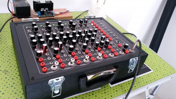
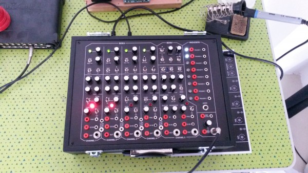
Simmons clone containing 4x sds3 and 1x sds5 channel + some extra's finally ready 
| Description: |
|
| Filesize: |
1.66 MB |
| Viewed: |
737 Time(s) |
| This image has been reduced to fit the page. Click on it to enlarge. |
|
| Description: |
|
| Filesize: |
1.74 MB |
| Viewed: |
1013 Time(s) |
| This image has been reduced to fit the page. Click on it to enlarge. |
|
_________________
http://www.soundcloud.com/arnoid
http://www.facebook.com/arnoid |
|
|
Back to top
|
|
|
xpmtl
Joined: Aug 10, 2007
Posts: 162
Location: Brussels, Belgium
|
| Posted: Wed May 20, 2015 11:51 am Post subject:
|
|
|
Very nice Arnoid
I finished mine aswell, been waiting to do a panel for almost 2 years will post pics this weekend.
@mono-poly : what's not working exactly? we can help you troubleshoot if you want.
_________________
http://sdiy.xpmtl.net |
|
|
Back to top
|
|
|
Jkuebler89
Joined: Apr 20, 2024
Posts: 6
Location: Portland
|
Posted: Wed May 08, 2024 7:53 pm Post subject:
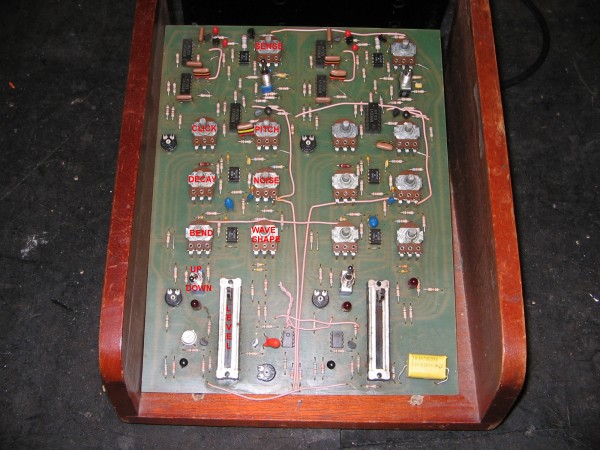
SDS-3 images of original circuit board?
Subject description: Anyone have some hi res images of the original circuit board? |
|
|
| I've seen some links in the forum for hi res images, but alas the link does not work, I even tried the wayback machine. Anyone have the images they can share? I would be forever grateful. This unit is so elusive. Thanks all. |
|
|
Back to top
|
|
|
Steveg

Joined: Apr 23, 2015
Posts: 184
Location: Perth, Australia
|
| Posted: Thu May 09, 2024 3:10 am Post subject:
|
|
|
| I can click on both of the above images and get a high rez version of each .... are you getting any errors? |
|
|
Back to top
|
|
|
Jkuebler89
Joined: Apr 20, 2024
Posts: 6
Location: Portland
|
| Posted: Thu May 09, 2024 8:20 am Post subject:
|
|
|
Sorry I'm a noob at the forums. Hi res photos of the original SDS-3 circuit board. Alex Ball has kindly given me some detailed images of the underside of the PCB, but as far as the top goes, for component values, I've found one image and it is super blurry.
I am looking for hi res image of the top of the circuit board. A few pages back someone shared that they own an SDS3 and posted a link but the link goes to a dead site.
Thank you! |
|
|
Back to top
|
|
|
ickystay
Joined: Nov 15, 2006
Posts: 143
Location: Oregon
|
|
|
Back to top
|
|
|
Jkuebler89
Joined: Apr 20, 2024
Posts: 6
Location: Portland
|
| Posted: Thu Jun 06, 2024 12:55 am Post subject:
|
|
|
Wow thank you. I was afraid this sub was dead but you came through!
I've got my pcb more or less working off THeffs work, but I am having similar issues to previous people's attempt with the ladder filter, I get a clean sine wave but my range is tiny on the tone side of potentiometer. And it is very high pitched. I am getting the smallest amount of tone frequency adjustment and the rest of the range only affects noise. I am wondering if my ladder filter is biased wrong. Would love to get this thing fully operational. Am open to any suggestions! Thank you. |
|
|
Back to top
|
|
|
|

 Forum index » DIY Hardware and Software