Posted: Sun Mar 25, 2012 7:50 am Post subject:
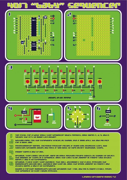
4017 Baby Sequencer Stripboard
Sequencers based upon the 4017 IC seem to be a right of passage many DIYers go through. I was recently asked about a stripboard layout for the infamous Baby Sequencer. Here are some diagrams which may be useful as a starting point...
I have tested this on breadboard and it seems to be working OK. Let me know if you find any mistakes and I'll correct the layout. Feel free to add to the circuit and modify it to your own needs.
BABY SEQUENCER V1.jpg
Description:
Filesize:
837.67 KB
Viewed:
17947 Time(s)
This image has been reduced to fit the page. Click on it to enlarge.
Hmm working on this right now, and so far i havent gotten it to work properly, only the first light seems to be showing a constant red shine, and no pulsing going on, have checked everyting seems to be something wrong.
Joined: May 17, 2012 Posts: 8 Location: San Francisco
Posted: Thu May 17, 2012 4:37 pm Post subject:
Will Try & Make This Sequencer
Hi Minus,
Thanks for posting this diagram of your sequencer. I am going to try and make it... this will probably sound like a dumb question, but what do the blue, light blue and green vertical lines represent ? Are they wires ? Also - In the far right of the third diagram you have a picture of a pot with a 1 Mo - does this mean a 1000 k pot ? thanks for your help... im sure that while I work on this I will be asking you more questions.. hope you don't get annoyed.
Joined: Oct 27, 2010 Posts: 594 Location: United Kingdom
Audio files: 64
Posted: Thu May 17, 2012 11:19 pm Post subject:
its 1mb
Potentiometers generally come in two flavours
linear (B) and logarithmic (A) they both have the same resistance but have different ways of getting there, a linear pot will work like
1 2 3 4 5 6 7 8 9 10
and a logarithmic pot would work like
0.1 0.2 0.5 0.9 1.5 2.5 3.8 5.5 7.5 10 (or probably even steeper, this is NOT a mathematically correct example)
the lines on the diagram are wires (jumpers) they make the "column" paths on the stripboard.
its unlikely that you will annoy people here so visit the chat room too, some helpful people in there _________________ _Richard_
I understand that the 555 is the clock source, but what all needs to be omitted to use an external clock source? Or where would switching jacks be added to allow switching between the two? Thanks!
I understand that the 555 is the clock source, but what all needs to be omitted to use an external clock source? Or where would switching jacks be added to allow switching between the two? Thanks!
Looks like pin 3 from the 555 outputs the clock source to pin 14 on the 4017. So I would guess adding a switching jack between those two will give the ability between external and internal clock.
If this will work, would you recommend a diode between the 555 and the switching jack to prevent pushing voltage into the 555 when switching to the external clock? Thanks!
Joined: May 17, 2012 Posts: 8 Location: San Francisco
Posted: Fri May 18, 2012 8:48 am Post subject:
bubzy wrote:
its 1mb
Potentiometers generally come in two flavours
linear (B) and logarithmic (A) they both have the same resistance but have different ways of getting there, a linear pot will work like
1 2 3 4 5 6 7 8 9 10
and a logarithmic pot would work like
0.1 0.2 0.5 0.9 1.5 2.5 3.8 5.5 7.5 10 (or probably even steeper, this is NOT a mathematically correct example)
the lines on the diagram are wires (jumpers) they make the "column" paths on the stripboard.
its unlikely that you will annoy people here so visit the chat room too, some helpful people in there
i thought that Mb and Kb were computing abbreviations (memory).. ?
Also - Im assuming that when I purchase the pots that they should be Linear for this project. / When I sodder the IC's do I need an IC Holder - I understand that you can destroy the IC's if you sodder them.. directly.
When I purchase the switches - I should get just on / off swithes.. not three position switches.. is this correct ?
I hope this helps..
M = Megohm
K = Kilohm
a = Logarithmic (Audio)
b = Linear (CV)
I always use sockets for my IC's. It can save loads of trouble is you mess up on your strip board. No desoldering and the IC's are reusable then.
Joined: May 17, 2012 Posts: 8 Location: San Francisco
Posted: Fri May 18, 2012 10:22 am Post subject:
baudrate wrote:
danbot wrote:
i thought that Mb and Kb were computing abbreviations (memory).. ?
Also - Im assuming that when I purchase the pots that they should be Linear for this project. / When I sodder the IC's do I need an IC Holder - I understand that you can destroy the IC's if you sodder them.. directly.
When I purchase the switches - I should get just on / off swithes.. not three position switches.. is this correct ?
I hope this helps..
M = Megohm
K = Kilohm
a = Logarithmic (Audio)
b = Linear (CV)
I always use sockets for my IC's. It can save loads of trouble is you mess up on your strip board. No desoldering and the IC's are reusable then.
Thanks Baudrate - when I purchase the sockets/ic holder do I simply need to know the types of IC's Im using or are all IC holders the same ? _________________ thank you - dan
I hadn't noticed the activity here! With the switches, just any on/off switch will be fine. Here's the switch abbreviations for future reference:
SP = Single Pole (One set of contacts only)
SPST = Single Pole Single Throw (or single changeover)
SPDT = Single Pole Double Throw
DPDT = Double Pole Double Throw
DP3T = Double Pole Triple Throw
4PDT = Four Pole Double Throw
*"Pole" = "Terminal" *"Throw" = "Position"
You could do an image search of each type to see what they look like in real life.
The GREEN jumper wire (figure 1) between points 'e' and 'd' is connecting the clock pulses coming out of the 555 timer at pin 3, to the clock input pin of the 4017 which is pin 14. If you want to stop and start the clock you need to leave OUT the GREEN jumper. Instead you add two wires at points 'd' and 'e' on the stripboard (figure 1), and connect to the switch or switches as shown in figure 6.
The BLUE jumper wire (figure 1) is there to reset the sequence count back to the first step after it runs through the 8 steps. If you look at the 4017 data sheet you can see how the pins are labelled. With the BLUE jumper in place it will count 1,2,3,4,5,6,7,8,1,2,3,4,5,6,7,8,1,2,3,4,5,6,7,8, etc.
BUT, that may not be what you what you want all the time. If you wanted just a 4 STEP pattern, the 5th output of the sequence would need to be tied to the 4017 reset pin (pin 15). With a rotary switch it is possible to select the amount of steps from 1 - 8 in your sequence.
As it stands with the BLUE and Green jumpers installed, you would have a basic 8 step sequencer. You can add features to this and modify it to your own needs. You could add switches to all of the pot outputs to turn steps ON/OFF. Turning down the pot at each step will do this anyway but you may want to turn the steps off without messing with your pot settings.
You can wire up a switched jack along the line from pin 3 of the 555 and pin 14 of the 4017 to use an external clock. Putting a diode in there from pin 3 before the jack may be a good idea.
Pots can be confusing. If you used logarithmic posts (type A) at the 8 steps, it would work but you'll find the range is all bunched up in the last 3rd of the pot rotation.
The BABY sequencer is a very basic one to build. It is a good introduction though to how sequencers work. And you can add to it as you learn more... a second row of pots perhaps, or pulse outputs. or triggers to fire drum modules.
Hope this helps!
EDIT: Sockets come in different sizes to match IC's. The 555 has 8 pins so you need an 8 pin socket. The 4017 has 16 pins, so you need a 16 pin socket. You can solder IC's directly to the board. They seem pretty robust. Just don't overheat them! Sockets are the best option. It's easy to pull out a chip and replace it if it may be faulty. Be careful pushing the IC's into the sockets. Make sure you don't bend any of the IC legs.
Joined: May 17, 2012 Posts: 8 Location: San Francisco
Posted: Fri May 18, 2012 6:59 pm Post subject:
-minus- wrote:
I hadn't noticed the activity here! With the switches, just any on/off switch will be fine. Here's the switch abbreviations for future reference:
SP = Single Pole (One set of contacts only)
SPST = Single Pole Single Throw (or single changeover)
SPDT = Single Pole Double Throw
DPDT = Double Pole Double Throw
DP3T = Double Pole Triple Throw
4PDT = Four Pole Double Throw
*"Pole" = "Terminal" *"Throw" = "Position"
You could do an image search of each type to see what they look like in real life.
The GREEN jumper wire (figure 1) between points 'e' and 'd' is connecting the clock pulses coming out of the 555 timer at pin 3, to the clock input pin of the 4017 which is pin 14. If you want to stop and start the clock you need to leave OUT the GREEN jumper. Instead you add two wires at points 'd' and 'e' on the stripboard (figure 1), and connect to the switch or switches as shown in figure 6.
The BLUE jumper wire (figure 1) is there to reset the sequence count back to the first step after it runs through the 8 steps. If you look at the 4017 data sheet you can see how the pins are labelled. With the BLUE jumper in place it will count 1,2,3,4,5,6,7,8,1,2,3,4,5,6,7,8,1,2,3,4,5,6,7,8, etc.
BUT, that may not be what you what you want all the time. If you wanted just a 4 STEP pattern, the 5th output of the sequence would need to be tied to the 4017 reset pin (pin 15). With a rotary switch it is possible to select the amount of steps from 1 - 8 in your sequence.
As it stands with the BLUE and Green jumpers installed, you would have a basic 8 step sequencer. You can add features to this and modify it to your own needs. You could add switches to all of the pot outputs to turn steps ON/OFF. Turning down the pot at each step will do this anyway but you may want to turn the steps off without messing with your pot settings.
You can wire up a switched jack along the line from pin 3 of the 555 and pin 14 of the 4017 to use an external clock. Putting a diode in there from pin 3 before the jack may be a good idea.
Pots can be confusing. If you used logarithmic posts (type A) at the 8 steps, it would work but you'll find the range is all bunched up in the last 3rd of the pot rotation.
The BABY sequencer is a very basic one to build. It is a good introduction though to how sequencers work. And you can add to it as you learn more... a second row of pots perhaps, or pulse outputs. or triggers to fire drum modules.
Hope this helps!
EDIT: Sockets come in different sizes to match IC's. The 555 has 8 pins so you need an 8 pin socket. The 4017 has 16 pins, so you need a 16 pin socket. You can solder IC's directly to the board. They seem pretty robust. Just don't overheat them! Sockets are the best option. It's easy to pull out a chip and replace it if it may be faulty. Be careful pushing the IC's into the sockets. Make sure you don't bend any of the IC legs.
Thanks Minus... I've printed your post for reference as I work on the project... when I'm all done I will post my results and probably post a YouTube video to boot. I will be coming back here ocasionally to ask more questions as I work on this.. hope you don't mind.. thanks again..
Joined: Jun 03, 2009 Posts: 65 Location: Sheffield
Posted: Wed Jul 25, 2012 3:47 pm Post subject:
How are people getting on with the 555 timer in there? I've been building up a big 4017 sequencer project, and found it wouldn't clock very well at high frequencies using a 555. A 4011 osc worked a treat, lets me take it up to really fast rates, can get some great cross-modulation style sounds with it! _________________ Circuit Bent Sonic Absurdity:
Joined: Dec 29, 2012 Posts: 3 Location: Asheville, NC
Posted: Sat Dec 29, 2012 5:37 pm Post subject:
Question about functionality
Sorry if this is an old thread.
I've built this sequencer as practice before I start on a 16-step design from MFOS. I wanted to be sure that the CV in on my Moog Rogue was functioning properly before undertaking a larger, more costly project.
So, the sequencer is built, the LEDs light in sequence and respond to adjustments on the timer. When I connect it to the Moog Rogue, the sequencer functions as normal as long as the next step in the sequence is a higher voltage, and on reset the sequence repeats with a higher baseline voltage. If the next step(s) in the sequence are a lower voltage, then the pitch will slowly glide down, but not nearly as fast or far as it should. Basically the Moog is acting like it's storing a charge from each step, thus increasing it's ground/reference voltage, and not resetting at each subsequent step.
I haven't had a chance to look at the sequencer's output on an oscilloscope yet, but my analog voltmeter responds as expected to the sequencer. Also, I connected a variable power supply to the Moog's CV in to verify that quick changes to the CV produce the expected pitch changes, and they do whether increasing or decreasing the voltage.
I'm puzzled by these observations. The sequencer and Moog seem to be functioning properly when used separately, but used together they do not.
Does anyone have any ideas of what may be going on? Or to those of you who have built this design, is this just a design flaw?
Joined: Mar 20, 2012 Posts: 2179 Location: Chicago
Audio files: 16
Posted: Sat Dec 29, 2012 7:22 pm Post subject:
Definitely sounds like you have some noticeable capacitance somewhere in there.
I would be interested in
1) does it do the same thing controlling any other CV controlled device (if you have another around)
2) do you have any other source of CV to test with the Moog?
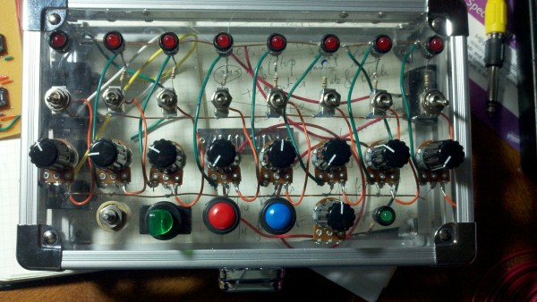
I've built this stripboard, but I want to put it into an enclosure that I haven't tried before so I've been working on other projects before completing this one.
Joined: Dec 29, 2012 Posts: 3 Location: Asheville, NC
Posted: Sun Dec 30, 2012 8:56 am Post subject:
The only other CV device I have is an analog voltmeter, which exhibits the expected behavior (sequencer seems to work as intended.)
I've used a variable power supply with the Moog. The result was snappy pitch response, nothing erratic or unexpected there.
Both devices seem to work alone, but not when used together.
Also, if I depress a low key on the moog in between steps of the sequencer, then the sequencer functions as intended.
Joined: Dec 29, 2012 Posts: 3 Location: Asheville, NC
Posted: Sun Dec 30, 2012 10:09 pm Post subject:
Heavy Metal Kid wrote:
Sounds like a legato mode problem, then?
Basically the envelope starts with a sharp attack, and drops very slowly to nil. The subsequent attack only registers if the previous envelope has dropped below the peak of the new envelope.
Joined: Mar 20, 2012 Posts: 2179 Location: Chicago
Audio files: 16
Posted: Thu Jan 03, 2013 10:07 pm Post subject:
Here's my crack at the enclosure for this stripboard, still in progress...
(ha ha notice the crack in the top if you look closely....)
I have added switches for gate, all the various optional pieces, and a quad AND chip to take gate and clock and generate a trigger of sorts. Going to take a clock out too just for completeness sake (since 4 jacks fit reasonably well along the side)
2013-01-03_22-53-42_869.jpg
Description:
Filesize:
2.21 MB
Viewed:
1403 Time(s)
This image has been reduced to fit the page. Click on it to enlarge.
2013-01-03_22-53-53_247.jpg
Description:
Filesize:
2.13 MB
Viewed:
1144 Time(s)
This image has been reduced to fit the page. Click on it to enlarge.
2013-01-03_22-53-18_110.jpg
Description:
Filesize:
2.07 MB
Viewed:
1477 Time(s)
This image has been reduced to fit the page. Click on it to enlarge.
Joined: Mar 20, 2012 Posts: 2179 Location: Chicago
Audio files: 16
Posted: Sat Jan 05, 2013 12:04 am Post subject:
Done wiring, but not working entirely. Will post video when it's uploaded/processed, but I'm having some issues with it. I've tried some mods to help, but they haven't really. Going to brain dump in case someone sees something that helps resolve the remaining problems....
So mods:
0) Did all the optional mods minus listed, pluse the switches for gate out as mentioned before
1) added clock/gate AND (with a 4081) to get a trigger out
2) ran a 47k resistor from 4017 reset to ground so it wasn't floating
3) ran a 10nF cap from 555 pin 5 to ground, per usual 555 circuits
4) Adjusted the component values; set the timing cap to 2.2uF and "R2" to 5k instead of 10k, so I could get things a little slower to my liking
5) ran the clock pulse through a 2N3904 inverter--this helps with #1 and also let's me send a clock out as well (so I could conceivably make this a clock source for some other simple project). Basically instead of being high all the time with downward pulses, it's the other way round. The 4017 doesn't care of course, but other things do.
Originally I just bolted the stripboard right up against the clear plastic (polycarbonate??) in this pencil box, but that seemed to make things REALLY unreliable, so I have used nuts as standoffs to get it just off the plastic. I don't have bolts long enough to get higher up, nor clearance above the board.
Even being more reliable, I still double/triple hit some notes and eventually get hung up on one. Most often this seems to be happening on step 5, but it is not always. Physically banging the box almost always resolves it, now that I have the PCB up off the plastic.
I don't think I have any lose bits of junk running around, and if I did I'd expect the banging to change the symptom entirely instead of ending up hanging in the same place (as I say, most of the time anyway).
Anyone have any ideas? I'm going to go over it more carefully tomorrow.
BTW earlier I had one of those moments: that sinking feeling when you realize you just wired your reset rotary backwards....
I'm impressed you built this, Elmegil. Thanks for the research once again. I'm yet to construct one of my own. I'm not sure how I missed the cap from pin 5 of the 555 to GROUND. I do see this in several 555 schematics now you have mentioned it. Any idea why this cap is needed?
I am unsure why your sequencer is 'sticking' on steps. I built a trigger sequencer a couple of years ago and didn't experience this problem. I seem to be caught up in real life BS at the moment so I can't see this or much other electronic building happening until the weather clears.
I'll get around to posting another diagram based on whatever is uncovered here, with the various mods included... hopefully this month.
EDIT: And the RESET is floating too! Sorry... . I'll have to fix this up.
Joined: Mar 20, 2012 Posts: 2179 Location: Chicago
Audio files: 16
Posted: Sat Jan 05, 2013 11:40 am Post subject:
I've tried grounding the case (not easy with an aluminum case but thin so I can't really put a significant screw into it, and that hasn't helped. I did discover that sometimes just touching the case will kick it loose. I also exhibit this problem even when not connected to the cigarlab.
Edit: I was also getting trigger outs to the cigarlab when there was no AND chip in! Definitely smelling like a ground problem somewhere. Hm...the copper wire I'm using as bus bar is old, and I did not strip it/clean it. I'm getting weird results testing ground connection on the board out to the bus bars....
Here's a bit about pin 5 (the control voltage; lets you voltage control some aspects of the behavior) from an application note by Phillips:
Quote:
For applications where the control
voltage function is not used, it is strongly recommended that a bypass capacitor (0.01μF) be placed across the control voltage pin and ground. This will increase the noise immunity of the timer to high frequency trash which may monitor the threshold levels causing timing error.
Essentially since the control voltage is normally set by an internal voltage divider, adding the cap will make it act as a low pass filter as well.
You cannot post new topics in this forum You cannot reply to topics in this forum You cannot edit your posts in this forum You cannot delete your posts in this forum You cannot vote in polls in this forum You cannot attach files in this forum You can download files in this forum

 Forum index » DIY Hardware and Software » The layout factory