| Author |
Message |
carlo64
Joined: Apr 02, 2020
Posts: 18
Location: Italia
|
 Posted: Sun Apr 19, 2020 4:42 am Post subject: Posted: Sun Apr 19, 2020 4:42 am Post subject:
|
  |
|
Hi,
unfortunately after making the change I find myself with distorted waves like the hedefalk user and I can no longer fix them ..  |
|
|
Back to top
|
|
 |
wackelpeter
Joined: May 05, 2013
Posts: 461
Location: germany
Audio files: 10
|
| Posted: Sun Apr 19, 2020 9:48 am Post subject:
|
|
|
Then perhaps try another LM13700 and as i looked into my outprint of the schematic i saw that i reduced R34 from 100K to 56K, at least i marked it on the paper...
_________________
https://soundcloud.com/bastian-j |
|
|
Back to top
|
|
|
carlo64
Joined: Apr 02, 2020
Posts: 18
Location: Italia
|
| Posted: Sun Apr 19, 2020 11:54 pm Post subject:
|
|
|
| wackelpeter wrote: | | Then perhaps try another LM13700 and as i looked into my outprint of the schematic i saw that i reduced R34 from 100K to 56K, at least i marked it on the paper... |
Thanks, I'll try this too. I will also try to find a power supply at 15 + 15 instead of 12 to also do some other tests.
Carlo |
|
|
Back to top
|
|
|
carlo64
Joined: Apr 02, 2020
Posts: 18
Location: Italia
|
| Posted: Tue Apr 21, 2020 12:39 am Post subject:
|
|
|
Ok! now I have a nice wide sine wave, but unfortunately when the frequencies go up I have all the waves very very distorted .. (the square becomes a trapezoid etc) will depend on the economic components
Thanks for support!
Carlo |
|
|
Back to top
|
|
|
wackelpeter
Joined: May 05, 2013
Posts: 461
Location: germany
Audio files: 10
|
| Posted: Tue Apr 21, 2020 2:00 am Post subject:
|
|
|
what fixed the sine?
and btw. can those distorted looks on your waveshapes come from your oscilloscope AC vs DC coupled?
_________________
https://soundcloud.com/bastian-j |
|
|
Back to top
|
|
|
carlo64
Joined: Apr 02, 2020
Posts: 18
Location: Italia
|
| Posted: Tue Apr 21, 2020 10:20 am Post subject:
|
|
|
| wackelpeter wrote: | what fixed the sine?
and btw. can those distorted looks on your waveshapes come from your oscilloscope AC vs DC coupled? |
R34 from 100K to 56K!
AC if I use analog oscilloscope, automatically if I use economic hantek connected to the PC.
I attach some pictures, as the frequency increases (say after 3/5 kHz) the distortion increases
(I'm not very good, I still have to learn ..)
triangular and square
high frequency


low frequency


Carlo |
|
|
Back to top
|
|
|
elmegil

Joined: Mar 20, 2012
Posts: 2179
Location: Chicago
Audio files: 16
|
| Posted: Tue Apr 21, 2020 10:56 am Post subject:
|
|
|
The mess in the middle looks like you haven't calibrated the triangle yet? (the "blip" near the zero crossing)
Going immediately to clipping on the sine shaper makes it look to me like whoever suggested this is trying to boost the signal *before* the shaper, and it's boosted WAY to much. Reduce how much you're boosting (dunno the specifics of the ckt at this very moment, and no time to go read up immediately).
edit: also looks like your triangle may not be centered about zero. That's another important calibration step. |
|
|
Back to top
|
|
|
carlo64
Joined: Apr 02, 2020
Posts: 18
Location: Italia
|
| Posted: Tue Apr 21, 2020 11:27 pm Post subject:
|
|
|
Hi Elmegil,
I don't have a trimmer to adjust the triangle, how should I do it?
Yes, maybe the sine wave is at the limit, I have to try a compromise with the resistance value.
Thank you |
|
|
Back to top
|
|
|
wackelpeter
Joined: May 05, 2013
Posts: 461
Location: germany
Audio files: 10
|
| Posted: Wed Apr 22, 2020 6:35 am Post subject:
|
|
|
Without looking too much into it, i tend to say that you can adjust the offset if you play around with the values of R17 and R21.
_________________
https://soundcloud.com/bastian-j |
|
|
Back to top
|
|
|
elmegil
Joined: Mar 20, 2012
Posts: 2179
Location: Chicago
Audio files: 16
|
| Posted: Wed Apr 22, 2020 7:01 am Post subject:
|
|
|
| I must be remembering the wrong TH VCO, I'd swear there were trimmers for offset and the bump. |
|
|
Back to top
|
|
|
carlo64
Joined: Apr 02, 2020
Posts: 18
Location: Italia
|
| Posted: Wed Apr 22, 2020 7:59 am Post subject:
|
|
|
| wackelpeter wrote: | | Without looking too much into it, i tend to say that you can adjust the offset if you play around with the values of R17 and R21. |
and I thought I had found a vco with few adjustments 
I will have to do some experiments!
Carlo |
|
|
Back to top
|
|
|
carlo64
Joined: Apr 02, 2020
Posts: 18
Location: Italia
|
| Posted: Wed Apr 22, 2020 8:02 am Post subject:
|
|
|
| elmegil wrote: | | I must be remembering the wrong TH VCO, I'd swear there were trimmers for offset and the bump. |
they would have helped me a lot
 |
|
|
Back to top
|
|
|
Aleencabralia
Joined: Feb 10, 2020
Posts: 5
Location: Brasil
|
| Posted: Sun Jul 12, 2020 8:02 pm Post subject:
|
|
|
Carlo, it was addressed in the previous page, it might be a fake op amp. Try and buy some tl074 from a trusted seller.
I built 3 of these and I´m having 2 problems: One is the tuning (Is my first osc built, so, pretty noob). I get the first 3 octaves, but the highr are sharp. I think I don´t get how the HF trimmer works: It´s like the calibration one? Like, when freq is flat, I move it even flatter, then go back, re-tune, repeat? Or it just "corrects" the freq? Tryed it in both extremes, HF are always sharp (When I tune them, The lower ones get flat). I matched the transistors using Ian Fritz method.
The other issue is that my sines are triangles! The round trim (I used a 50k in one and 100k in the other 2) just lower the amplitude a bit, the other one doesn´t seem to do anything!!
Any help is really welcome. |
|
|
Back to top
|
|
|
NuttyMonk
Joined: Jun 30, 2020
Posts: 63
Location: UK
|
| Posted: Tue Jul 21, 2020 5:16 pm Post subject:
|
|
|
| fonik wrote: |
anyways, here is a picture of a PTC mounted on top of a super matched pair for a 555VCO. i think you get the idea:

Thanks a lot! |
Hi Fonik, love the way you have done the thermal mating here. What is the metal cap you used? Are they easy to come by?
On another matter i have a question about the "Sine Round Trim R24" trimpot in the schematic. Is it wired through directly as shown there with nothing connected to the wiper? If so it won't be a voltage divider and it also won't be a variable resistor. What gives? I'm relatively new to electronics so maybe i'm missing something obvious about how this is drawn and what it means.
Cheers |
|
|
Back to top
|
|
|
wackelpeter
Joined: May 05, 2013
Posts: 461
Location: germany
Audio files: 10
|
| Posted: Wed Jul 22, 2020 1:58 am Post subject:
|
|
|
The trimmer is connected with two pins one of it's outer legs, and the wiper with the other outer leg conected together. Doesn't matter which one you're usig only the direction of the resistance getting higher or smaller would be the opposite.
Common practive to not keep legs on resistors or trimmers unconnected or floating... So the unused leg will simply be connected to the wiper...
_________________
https://soundcloud.com/bastian-j |
|
|
Back to top
|
|
|
NuttyMonk
Joined: Jun 30, 2020
Posts: 63
Location: UK
|
| Posted: Wed Jul 22, 2020 8:09 am Post subject:
|
|
|
Thanks wackelpeter. I understand. I've seen that before in schematics and wondered about it but it makes sense. I guess it prevents the possibility of interference on the floating leg of the pot.
Thanks for the quick reply.
Cheers
NM |
|
|
Back to top
|
|
|
carlo64
Joined: Apr 02, 2020
Posts: 18
Location: Italia
|
| Posted: Sun Aug 02, 2020 11:43 pm Post subject:
|
|
|
Resolved! I replaced the tl074 (new grrr) with old recovery smd with an adapter and now the waveforms are perfect. (just some small difference in output level but I'm happy!)
Thanks Aleencabralia and thanks to everyone!
Carlo
 |
|
|
Back to top
|
|
|
injektilo001
Joined: Aug 21, 2020
Posts: 10
Location: Chile
|
| Posted: Sat Sep 19, 2020 7:59 am Post subject:
SINGLE SIDED PCB |
|
|
Hello Everyone, I'm Jean Paul from Chile
I was wondering if somebody has a working single sided PCB and layout from this beautifull VCO for etching myself?
I've been looking like crazy everywhere.
(If somebody has the same kind of files for the Thomas Henry X-4046 it will be wonderfull too).
Hope somebody can help
Cheers from Chile |
|
|
Back to top
|
|
|
warpeggio
Joined: Oct 14, 2020
Posts: 9
Location: St. Louis, Missouri, USA
|
| Posted: Sun Dec 13, 2020 1:56 pm Post subject:
|
|
|
Greetings, fellow synth nerds!
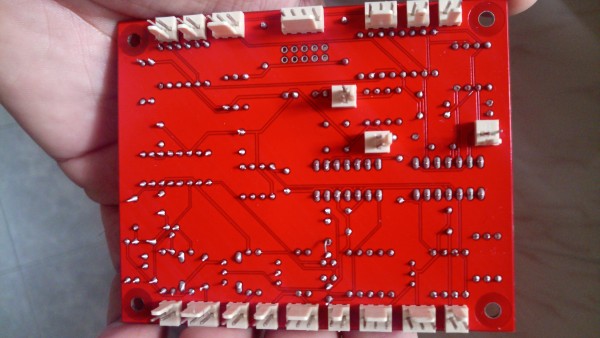
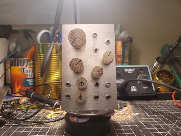
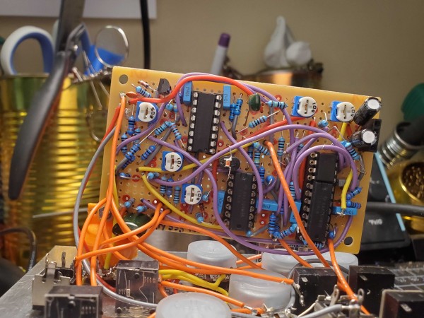
I've made a stripboard layout for Thomas' design. I was running low on stripboards in my parts bin, so my goal was to fit the whole shebang onto a single 93x55mm stripboard. I think the result will make some folks bristle, as I've broken some of the usual layout rules. However, i can confirm this layout works, as i've spent the weekend with it on my bench.
When constructing this board, my method was to work from left to right across the board, soldering 2-5 components at a time, which allows me to build up clusters of components relatively easily. The area around R14 and R32 is particularly prone to shorts, among some other areas. When you see that component legs may come together like that, its a good idea to slip some wire insulation over the component leads. You'll see examples of this on my board.
I will admit that i made errors both in the draft layout, and in my construction. Friends, you must stick with troubleshooting to get far in this hobby! My draft was missing 1 jumper wire, and 3 trace cuts on the left side of R36. The trace cut issues nearly overheated IC3. I made a construction error of omitting the jumper that ties the emitters of Q2/Q3 together, which resulted in the circuit having a narrow oscillation range in the supersonic.
Sorting all these issues out, the build tracked 1v/Oct nearly effortlessly. I am getting 5 octaves now with my inaccurate CV source. I will update when i am able to test with a precise CV input.
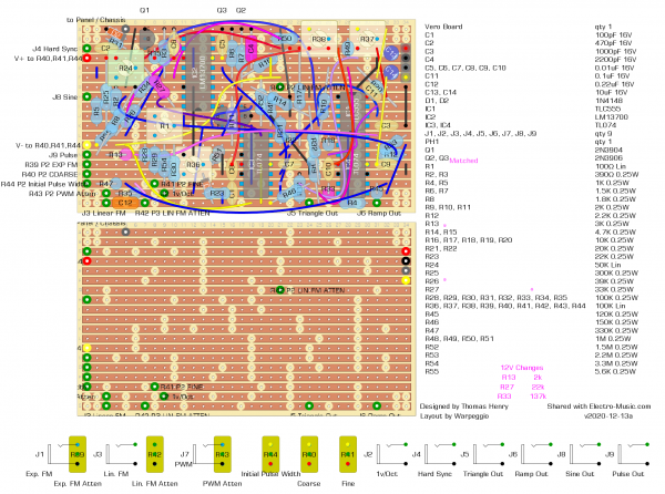
The BOM shows values for 15V supply as in the original schematic. The values for 12V supply are provided as well. Also, per Fonik's PCB notes, i've used his part numbering for R25, R26, and R55.
Changelog
v2020-12-13a: The colors on the power connector (PH1) on the right side of the board were wrong. This has been corrected.
v2020-12-13: Initial upload
| Description: |
|
| Filesize: |
561.82 KB |
| Viewed: |
205 Time(s) |
| This image has been reduced to fit the page. Click on it to enlarge. |
|
| Description: |
|
| Filesize: |
661.91 KB |
| Viewed: |
233 Time(s) |
| This image has been reduced to fit the page. Click on it to enlarge. |
|
| Description: |
|
| Filesize: |
508.96 KB |
| Viewed: |
287 Time(s) |
| This image has been reduced to fit the page. Click on it to enlarge. |
|
|
|
|
Back to top
|
|
|
NathanS
Joined: Sep 13, 2020
Posts: 3
Location: Iowa, USA
|
| Posted: Thu Jan 28, 2021 7:25 pm Post subject:
Refactored Schematic |
|
|
Some time ago I was taking an electronics course for a physics degree and was allowed to do an analysis of this circuit for the final project. This involved both bread-boarding the circuit, as well as writing a paper describing how it worked.
One of the things that resulted from this was a KiCad schematic which I've done quite a bit of tinkering on in an attempt to decompose it into its core functions. It has been my intention to make a real nice PCB from it as well; though the few attempts I've made haven't resulted in nice enough boards to make me want to give out those files as well --- not yet anyway.
Regardless, I figured I'd give out the schematic so far in the hope that it would save someone a ton of time if they had plans to transcribe the original to digital. Also included is a PDF print-out, in case someone is interested in seeing it without using KiCad.
I'd be interested in hearing any recommendations for modifications to the file to make it more understandable or more generalized. There is currently a lot more space for comments to be added, and I'm sure it could be used well.
Edit (2021-02-03): Changed out PDF to a properly formatted version that allows text selection. Updated the KiCad schematic to the version the PDF was plotted from. The only diffs in the schematic file are of a couple of connectors (J2, J3).
Edit (2021-08-16): Fixed wrongly connected wire in the sawtooth shaping sub-circuit. R20 was connected to U4 through pin 2, where it should have been connected to pin 7. It was making some interesting ramps, anyway... 
The schematic as a whole was revised. It's a bit more organized and hopefully more understandable as a result. A few more references were linked in, and my notes were expanded on a bit. R27 and R24 were changed based on Fonik's suggestion a ways back in the thread. Lastly, the OTA's unused buffer's input was grounded - which I'm hesitant to claim makes any difference.
I did make a PCB using this version which I just finished putting through its paces. I haven't checked how well it tracks, but it sounded good and I'm reasonably confident no major bugs are present at the schematic level now.
| Description: |
|

Download (listen) |
| Filename: |
Thomas_Henry_555VCO.pdf |
| Filesize: |
134.38 KB |
| Downloaded: |
2994 Time(s) |
| Description: |
|
Download (listen) |
| Filename: |
Thomas_Henry_555VCO.sch |
| Filesize: |
57.75 KB |
| Downloaded: |
307 Time(s) |
Last edited by NathanS on Mon Aug 16, 2021 2:41 pm; edited 3 times in total |
|
|
Back to top
|
|
|
wallybob
Joined: Sep 26, 2015
Posts: 7
Location: Iowa
|
| Posted: Fri Jan 29, 2021 7:55 am Post subject:
|
|
|
| Thanks a lot for posting the KICAD schematic file for this! |
|
|
Back to top
|
|
|
Alfredo
Joined: Nov 20, 2008
Posts: 52
Location: Spain
|
| Posted: Sun Feb 07, 2021 1:18 pm Post subject:
Tuning issue |
|
|
I have this board that someone gave me for free. Look very similar to the Fonik one and sound fantastic, all potentiometers work as it should as well as the modulation inputs. Only problem is I can't calibrate because the HF trim R36 doesn't do nothing,maybe the person who designed the board made a mistake, anyway my knowledge is not sufficient to detect the problem.
I show you some images of the plates in case someone can see the problem.
Any help appreciated, thanks!
https://www.youtube.com/watch?v=co-Rp9sCECs
| Description: |
|
| Filesize: |
2.79 MB |
| Viewed: |
252 Time(s) |
| This image has been reduced to fit the page. Click on it to enlarge. |

|
| Description: |
|
| Filesize: |
3.72 MB |
| Viewed: |
242 Time(s) |
| This image has been reduced to fit the page. Click on it to enlarge. |

|
| Description: |
|
| Filesize: |
4.31 MB |
| Viewed: |
247 Time(s) |
| This image has been reduced to fit the page. Click on it to enlarge. |

|
|
|
|
Back to top
|
|
|
elmegil
Joined: Mar 20, 2012
Posts: 2179
Location: Chicago
Audio files: 16
|
| Posted: Sun Feb 07, 2021 2:03 pm Post subject:
|
|
|
Did you mirror your bottom-side scan around with software? Normally there's no way to scan it so that the holes on one side line up directly with the holes on the other, but that's what it looks like to me.
So the circled leg of R36 is supposed to be ground, it ties to D2 where D2 is also supposed to be ground. I would verify the continuity between those two points, that your solder joint there was good, and that both points show continuity to ground. That would be the most likely cause for a problem.
If that all seems correct, next thing would be to measure the cathode of D1 when things are powered on and verify that you're seeing control voltage there, that tracks the linear FM input with the pot all the way up. Then measure the wiper of the trimmer and make sure that it's changing when you turn the trimmer. It is possible that the trimmer is defective if your solder joints are solid and it doesn't do anything. |
|
|
Back to top
|
|
|
NathanS
Joined: Sep 13, 2020
Posts: 3
Location: Iowa, USA
|
| Posted: Sun Feb 07, 2021 2:16 pm Post subject:
|
|
|
It looks to me as if R2 and R23 should be swapped around. At least according to the original schematic, R2 should go to ground and the trimmer R1, but it's going out to D1 and IC3-pin7 - as R23 should.
Thus in that pcb, R2 should be 22 kOhm while R23 should be 390 Ohm. Does this match up with how it's been put together? |
|
|
Back to top
|
|
|
Alfredo
Joined: Nov 20, 2008
Posts: 52
Location: Spain
|
|
|
Back to top
|
|
|
|

 Forum index » DIY Hardware and Software » Thomas Henry designs