| Author |
Message |
6079smith
Joined: Jan 18, 2007
Posts: 95
Location: Mark of the Dane
Audio files: 4
|
 Posted: Thu Mar 26, 2009 2:45 pm Post subject: Posted: Thu Mar 26, 2009 2:45 pm Post subject:
|
  |
|
Sorry, I was thinking of another LED thing I did on the Wogglebug I made - a bicolour on the woggle tone output.
Which version are you using? If it's Richard Brewster's version, I can see there's a transistor inverter just before the output buffer for the clock output... maybe you could take the driver input from just before that? |
|
|
Back to top
|
|
 |
Audent

Joined: Dec 19, 2007
Posts: 24
Location: oh-hi-oh
|
|
|
Back to top
|
|
|
sduck

Joined: Dec 16, 2007
Posts: 459
Location: Nashville
Audio files: 5
|
| Posted: Tue Mar 16, 2010 3:08 pm Post subject:
|
|
|
Sorry to resurrect this thread once again (actually I'm not really that sorry)!
I'm having the same problem xpmtl had. Did he ever get it sorted out? I just built 2 more bugs with the group buy pcb's, with the idea of having them behind a dual panel with all the extra features found in the wiard version. With both of the first 2 I built, I didn't wire up the lfo out jack, but I have with these new ones. However, the output seems pretty useless - stuck at 5v, with little dips to about 4v at the clocks (like the diagram xpmtl put up a page back) - seems inverted from what it should be.
And I'd also like to wire up an led from the lfo rate with the cgs pcb, but with that always-on voltage, the led doesn't really do much. I'm going to try some alternate places to connect the sensor wire for the led, but I'd still like to sort out the lfo out problem to make it usable.
Any ideas?
Edit: bump - I hope someone has some ideas about this! |
|
|
Back to top
|
|
|
sduck
Joined: Dec 16, 2007
Posts: 459
Location: Nashville
Audio files: 5
|
| Posted: Wed Mar 17, 2010 2:55 pm Post subject:
|
|
|
| I tried running the lfo out through my cgs inverter and got the behavior I expected - short positive 5v pulses at the clock, 0v in between, and the led behaving correctly. So as the circuit is really simple, I'll just breadboard up 2 of those and hook them up behind the panel. |
|
|
Back to top
|
|
|
davebr

Joined: Jun 09, 2007
Posts: 198
Location: portland, or
|
Posted: Thu Mar 18, 2010 12:35 pm Post subject:
Wogglebug circuit
Subject description: potentiometer taper |
|
|
What are people using for the 1M potentiometer taper?
I'm thinking log would work best.
Dave |
|
|
Back to top
|
|
|
sduck
Joined: Dec 16, 2007
Posts: 459
Location: Nashville
Audio files: 5
|
| Posted: Thu Mar 18, 2010 3:24 pm Post subject:
|
|
|
| I used linear ones, but now that you mention it, log ones might work better - there seems to be lot more change near the top end of the rotation. However, given the random nature of the device, getting a precision setting on the dials is of a low priority for me, so I won't be changing them out to see if it makes a difference. |
|
|
Back to top
|
|
|
davebr
Joined: Jun 09, 2007
Posts: 198
Location: portland, or
|
Posted: Fri Mar 26, 2010 11:48 am Post subject:
Wogglebug
Subject description: Added a web page |
|
|
I've started building my Wogglebug PCB. I've created a web page with a Mouser part number list, photos, and other information. I'll continue to update it as I complete the module. Since I'm still building the PCB I haven't yet verified all the parts.
I was unable to find a set of schematics with the correct pin and reference information for U5, U6, and U7 so I edited the schematics myself. I also included the stability modification for U3. I posted this update on my web page (let me know if they already exist somewhere on the web).
So far I've only implemented two additional modifications - changing the LFO Out to a Clock Out, and adding a LED indicator for the Clock Out. The LFO Out was a +/- 5 volt 7.4 mS negative pulse that I thought would be more useful as a 0 to +5 volt positive pulse to use as a variable clock / trigger generator.
http://modularsynthesis.com/bridechamber/wb/wb.htm
Dave |
|
|
Back to top
|
|
|
sduck
Joined: Dec 16, 2007
Posts: 459
Location: Nashville
Audio files: 5
|
| Posted: Fri Mar 26, 2010 1:49 pm Post subject:
|
|
|
Very nice! I'm guessing you haven't gotten around to adding the cluster cap cludge to your list of add-ons - I'm pretty sure you know what I mean. Every one of mine has needed it to get the cluster knob working.
Edit - oops, now that you mention it I see you had it there all along. Sorry.
Last edited by sduck on Sat Mar 27, 2010 7:41 pm; edited 2 times in total |
|
|
Back to top
|
|
|
davebr
Joined: Jun 09, 2007
Posts: 198
Location: portland, or
|
Posted: Fri Mar 26, 2010 5:08 pm Post subject:
Wogglebug Circuit
Subject description: Modifications |
|
|
| sduck wrote: | | Very nice! I'm guessing you haven't gotten around to adding the cluster cap cludge to your list of add-ons - I'm pretty sure you know what I mean. Every one of mine has needed it to get the cluster knob working. |
I noted that additional modification on my web site.
I'm debating about whether I want to modify the Smooth, Woggle, and Stepped CV outputs to 5 volt range rather than the 10 volt range. I thought I would wait and see how well I like it with 10 volt range but that seems pretty large. Any thoughts?
Dave |
|
|
Back to top
|
|
|
davebr
Joined: Jun 09, 2007
Posts: 198
Location: portland, or
|
| Posted: Fri Mar 26, 2010 6:33 pm Post subject:
|
|
|
| xpmtl wrote: | hi all,
I'm trying to add the cgs led driver to the clock out but i got into trouble as the pulse seems inverted.
The led is bright all the time and goes off for a micro-second. Anyone got the same results?
Do I have to use an inverter or is there a simplier way to solve that?
Pulse looks like the first one in the image attached, for correct operation it should be like the second i think.
thanks |
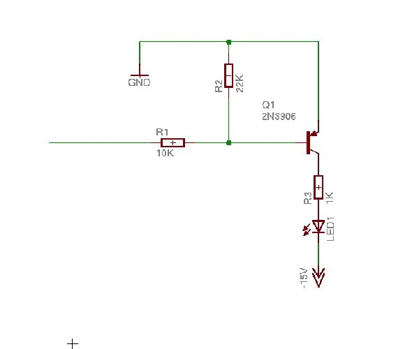
A CMOS 555 can sink quite a bit of current, so it can drive the LED directly. Connect the anode to +15 volts, and the cathode through a 3K3 resistor to pin 3 of U4. It will turn on the LED only for those short pulses and behave exactly as you want.
Sorry for the late response. I just got my wogglebug PCB so I am now just getting familiar with it.
Dave |
|
|
Back to top
|
|
|
sduck
Joined: Dec 16, 2007
Posts: 459
Location: Nashville
Audio files: 5
|
| Posted: Fri Mar 26, 2010 7:03 pm Post subject:
|
|
|
| I've never considered the range of the cv outs to be too much. I'd leave them at 10v - you can always attenuate them down if desired. |
|
|
Back to top
|
|
|
davebr
Joined: Jun 09, 2007
Posts: 198
Location: portland, or
|
Posted: Fri Mar 26, 2010 9:11 pm Post subject:
Wogglebug
Subject description: Output levels |
|
|
| sduck wrote: | | I've never considered the range of the cv outs to be too much. I'd leave them at 10v - you can always attenuate them down if desired. |
I decided to add jumpers for either 0 - 5 volts or 0 - 10 volts. That way I can easily change it. I've finished the module and have photos on my web page.
http://modularsynthesis.com/bridechamber/wb/wb.htm
Dave |
|
|
Back to top
|
|
|
davebr
Joined: Jun 09, 2007
Posts: 198
Location: portland, or
|
Posted: Tue Apr 06, 2010 4:05 pm Post subject:
Wogglebug
Subject description: 50% duty clock out |
|
|
After using my Wogglebug for a bit, I decided I wanted the clock out to be a 50% duty cycle. The rate is plenty fast so I decided to divide the output of the 555 by two to generate a square wave. I made a module using an 8 pin DIP header, a LM555C, and a 74C74 that plugs right in place of U4 so there are no modifications to the PCB. Three of the 74C74 pins line up with the LM555C so there are just a few pins to hand wire.

I added the details to my Wogglebug page.
http://modularsynthesis.com/bridechamber/wb/wb.htm
Dave |
|
|
Back to top
|
|
|
slacker
Joined: Nov 18, 2007
Posts: 301
Location: England
Audio files: 11
G2 patch files: 1
|
| Posted: Wed Apr 07, 2010 10:13 am Post subject:
|
|
|
That's brilliant Dave  |
|
|
Back to top
|
|
|
xpmtl

Joined: Aug 10, 2007
Posts: 162
Location: Brussels, Belgium
|
|
|
Back to top
|
|
|
sduck
Joined: Dec 16, 2007
Posts: 459
Location: Nashville
Audio files: 5
|
| Posted: Wed Apr 07, 2010 7:21 pm Post subject:
|
|
|
| Thanks! But I went ahead and made a little inverter board and hard wired it back there, and it works great. I only discovered the problem after I had installed everything, and using the addon board made a little more sense than taking the whole thing apart. I knew the addon board was going to work, and I wasn't so sure about the other kind of fix, so the choice wasn't too hard. However, I'm sure your fix will help someone else down the road, so it's all good! |
|
|
Back to top
|
|
|
tommi

Joined: Dec 05, 2007
Posts: 247
Location: Italy
Audio files: 3
|
| Posted: Thu May 06, 2010 9:32 am Post subject:
|
|
|
Since i am waiting for a PCB from bridechamber i am documenting myself for all possible modifies for the wogglebug. I 've seen different solutions for the clock rate led. The simplest seems to be the one from davebr: 3k3 resistor from pin3 of U4 (lm555) to cathode, +V to anode. I think i 'll try this one.
Also, as written by sduck on the top of this page:
| Quote: | | With both of the first 2 I built, I didn't wire up the lfo out jack, but I have with these new ones. However, the output seems pretty useless - stuck at 5v, with little dips to about 4v at the clocks (like the diagram xpmtl put up a page back) - seems inverted from what it should be. |
I would like to have an lfo out jack on my panel to use as trigger out for ADSRs, drum modules or even to clock sequencers. Anybody can point me to a circuit i can use?
On this scheme posted by xpmtl is the 10k supposed to be linked to pin3 of U4?
_________________
http://soundcloud.com/mister-vommi
http://tideofsound.net |
|
|
Back to top
|
|
|
davebr
Joined: Jun 09, 2007
Posts: 198
Location: portland, or
|
| Posted: Thu May 06, 2010 9:53 am Post subject:
|
|
|
| tommi wrote: | I would like to have an lfo out jack on my panel to use as trigger out for ADSRs, drum modules or even to clock sequencers. Anybody can point me to a circuit i can use?
|
I inverted my LFO output so it would be a positive pulse instead of a negative pulse to use it as a trigger output. It is a fixed 7.4 mS pulse and there is a scope image on my site.
After doing this and playing with it a while, I later changed it to a 50% duty cycle square wave. I left the inversion since it was already done but this would be unnecessary with the 50% duty cycle mod. It did, however, make the green LED indicate the positive portion of the waveform (LED=on when the 555 timer output is low).
Details of my mods are on my site.
http://modularsynthesis.com/bridechamber/wb/wb.htm
For a fixed pulse-width trigger, modify U6A to the circuit modification #6.
For a 50% duty cycle, just do the circuitry in modification #10. You can connect the LED to the /Q output (LED=on when /Q low, which makes Q high, and with standard U6A circuit makes LFO out high).
Dave |
|
|
Back to top
|
|
|
tommi
Joined: Dec 05, 2007
Posts: 247
Location: Italy
Audio files: 3
|
| Posted: Thu May 06, 2010 11:48 am Post subject:
|
|
|
Thanks davebr, i think i 'll do the inverter modification, it will do the job of triggering out short pulses for sequencers, etc.
The 555 will still be clocking U3(LF398) thru R27. In place of R40 (49,9K) there will be a 300k resistor. Another 300k resistor from +in to -V. One 100k on the feedback path and the -in to ground. Is that right?
Is it tricky to do? How many traces to cut?
_________________
http://soundcloud.com/mister-vommi
http://tideofsound.net |
|
|
Back to top
|
|
|
davebr
Joined: Jun 09, 2007
Posts: 198
Location: portland, or
|
| Posted: Thu May 06, 2010 4:15 pm Post subject:
Wogglebug LFO modifications |
|
|
| tommi wrote: | Thanks davebr, i think i 'll do the inverter modification, it will do the job of triggering out short pulses for sequencers, etc.
The 555 will still be clocking U3(LF398) thru R27. |
Correct
| tommi wrote: | | In place of R40 (49,9K) there will be a 300k resistor. |
Correct
| tommi wrote: | | Another 300k resistor from +in to -V. |
I just noticed that I got the + and - inputs backwards for the mod on my website. The 300K is to the - input and you should be able to use R8.
| tommi wrote: | | One 100k on the feedback path and the -in to ground. Is that right? |
I swapped the + and - inputs so the + input is grounded. Take a look at the updated modification and I think it will be clear.
| tommi wrote: | | Is it tricky to do? How many traces to cut? |
I'm afraid I didn't take very good notes. I made 3 cuts but in looking at it, I think you only need to make 2.
You have to cut the feedback loop from pin 1 to 2. That is on the top layer. R27 [error - should be R26] stays connected to pin 1.
You have to cut the input to pin 3. I did so under R8.
Then you have to connect the junction of R40/R8 to pin 2. You have to add a 100K feedback resistor (on the back) between pins 1 and 2. You have to ground pin 3.
That should do it. I think I used R8 as the feedback resistor so the third cut was the -15V . Using R8 as the other 300K resistor eliminates one cut. I didn't take a photo of the modification.
Dave
Last edited by davebr on Fri May 07, 2010 7:24 am; edited 1 time in total |
|
|
Back to top
|
|
|
tommi
Joined: Dec 05, 2007
Posts: 247
Location: Italy
Audio files: 3
|
| Posted: Fri May 07, 2010 1:43 am Post subject:
|
|
|
Thanks dave,
Looking at your picture of the populated board ( i was searching for details of your mod) it seemed to me that this modification wasn't yet done.
Anyway, in your answer it's all clear for me except for you said that R27 stays connected to pin 1.
On your WB's schematic R27 is linked to the 555's out on pin 3, not to pin1 of U6 (this is what i thought you was saying?).
I guess you was meaning that R26 stays linked to U6, pin1?
_________________
http://soundcloud.com/mister-vommi
http://tideofsound.net |
|
|
Back to top
|
|
|
davebr
Joined: Jun 09, 2007
Posts: 198
Location: portland, or
|
| Posted: Fri May 07, 2010 7:18 am Post subject:
Wogglebug modification |
|
|
| tommi wrote: | | Looking at your picture of the populated board ( i was searching for details of your mod) it seemed to me that this modification wasn't yet done. |
Correct.
| tommi wrote: | In your answer it's all clear for me except for you said that R27 stays connected to pin 1. On your WB's schematic R27 is linked to the 555's out on pin 3, not to pin1 of U6 (this is what i thought you was saying?).
I guess you was meaning that R26 stays linked to U6, pin1? |
Yes, sorry.
Dave |
|
|
Back to top
|
|
|
tommi
Joined: Dec 05, 2007
Posts: 247
Location: Italy
Audio files: 3
|
| Posted: Fri May 07, 2010 8:27 am Post subject:
|
|
|
Dave,
Since the led it's directly linked to the out of U4 (pin3), i think that in case of external clocking it will still indicate the rate of the internal clock. This would be distracting...
I thought i could add an led circuit (cgs led driver?) to pin7 of U6B (the amp stage of clock in) to indicate the actual rate at wich the circuit is clocked.
Maybe i am wrong on the interpretation of how your led is ment to behave?
_________________
http://soundcloud.com/mister-vommi
http://tideofsound.net |
|
|
Back to top
|
|
|
davebr
Joined: Jun 09, 2007
Posts: 198
Location: portland, or
|
| Posted: Fri May 07, 2010 8:40 am Post subject:
|
|
|
| tommi wrote: | Dave,
Since the led it's directly linked to the out of U4 (pin3), i think that in case of external clocking it will still indicate the rate of the internal clock. This would be distracting...
I thought i could add an led circuit (cgs led driver?) to pin7 of U6B (the amp stage of clock in) to indicate the actual rate at wich the circuit is clocked.
Maybe i am wrong on the interpretation of how your led is ment to behave? |
You have two choices - have the LED follow the internal clock or the wogglebug clock. I wanted to use the LFO for a clock generator for my CVS modules (that is why there are three LFO outputs) so I had the LED follow the internal generator. If I am driving the Wogglebug from an external clock source, that source will have an LED indicating the rate.
You can wire it up after U6B so it will follow the Wogglebug rate whether it is internally or externally generated. There are a couple of different ways to do that. One way would be to add a LED in series with D3 and change R20 to set the appropriate current (you could replace D3 with a LED if it had a 15 volt reverse voltage spec).
Dave |
|
|
Back to top
|
|
|
tommi
Joined: Dec 05, 2007
Posts: 247
Location: Italy
Audio files: 3
|
| Posted: Fri May 07, 2010 8:53 am Post subject:
|
|
|
| Quote: | One way would be to replace D3 with a LED and change R20 to set the appropriate current.
|
You ment that I could change R32(20K), maybe lowering it to make the led brighter? Are you sure that lowering the value of that resistor wouldn't affect some way the clocking of the S&H chip, i mean that it maybe could lower the level of the square wave?
_________________
http://soundcloud.com/mister-vommi
http://tideofsound.net |
|
|
Back to top
|
|
|
|

 Forum index » DIY Hardware and Software