| Would you buy a Jh Trapezoid VCA PCB? |
| no - only interested in the original EMS circuit (this is not goint to happen - sorry) |
|
2% |
[ 1 ] |
| yes - if it emulates the behaviour of the EMS circuit, and doesn't need component selecting |
|
97% |
[ 40 ] |
|
| Total Votes : 41 |
|
| Author |
Message |
jhaible

Joined: May 25, 2007
Posts: 2014
Location: Germany
Audio files: 24
|
 Posted: Fri Nov 26, 2010 12:43 pm Post subject: Posted: Fri Nov 26, 2010 12:43 pm Post subject:
|
  |
|
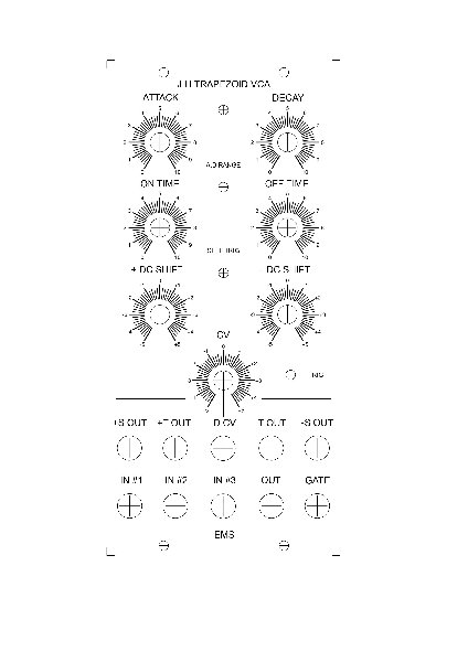
| zarko wrote: | Hi Jurgen, i made a new front panel with the attenuator pot,would you tell
me what do you think about  |
Looks great.
And you could still improove it by making it a reversible attenuator, i. e. zero at 12 o'clock position, and increasing Decay time on cw end (with a positive CV), decreasing decay time on ccw end.
Also, the DC shift potentiometers have no effect in 12 o'clock position. Turning them cw will add a positive DC shift, and turning them ccw will add a nagative DC shift. This refers to both pots: The "+" and "-" means the normal and the inverted output. You can DC-shift them both in both directions.
JH.
_________________
"I tell you the truth, if anyone says to this mountain, 'Go, throw yourself into the sea,' and does not doubt in his heart but believes that what he says will happen, it will be done for him. Therefore I tell you, whatever you ask for in prayer, believe that you have received it, and it will be yours." (Mk 11,23f) |
|
|
Back to top
|
|
 |
zarko
Joined: Mar 25, 2010
Posts: 22
Location: France
|
|
|
Back to top
|
|
|
jhaible
Joined: May 25, 2007
Posts: 2014
Location: Germany
Audio files: 24
|
| Posted: Fri Nov 26, 2010 3:51 pm Post subject:
|
|
|
Looks great! 
JH.
_________________
"I tell you the truth, if anyone says to this mountain, 'Go, throw yourself into the sea,' and does not doubt in his heart but believes that what he says will happen, it will be done for him. Therefore I tell you, whatever you ask for in prayer, believe that you have received it, and it will be yours." (Mk 11,23f) |
|
|
Back to top
|
|
|
numbertalk

Joined: May 05, 2008
Posts: 992
Location: Austin, TX
Audio files: 5
|
| Posted: Fri Dec 03, 2010 5:52 pm Post subject:
|
|
|
| Not sure if anyone's keeping track or adding fixes to the BOM that got created here anymore, but found 2 more errors - there's a 91K resistor missing and a 3K resistor listed that's supposed to be 2K4. |
|
|
Back to top
|
|
|
zarko
Joined: Mar 25, 2010
Posts: 22
Location: France
|
|
|
Back to top
|
|
|
numbertalk
Joined: May 05, 2008
Posts: 992
Location: Austin, TX
Audio files: 5
|
| Posted: Mon Dec 06, 2010 10:20 am Post subject:
|
|
|
| zarko wrote: | Hi
I think that the right value is 3K on the PCB |
Yeah, I saw that on the web site image too, but my board has 2K4 there, as well as the schematic. JH? |
|
|
Back to top
|
|
|
jhaible
Joined: May 25, 2007
Posts: 2014
Location: Germany
Audio files: 24
|
| Posted: Mon Dec 06, 2010 1:18 pm Post subject:
|
|
|
| numbertalk wrote: | | zarko wrote: | Hi
I think that the right value is 3K on the PCB |
Yeah, I saw that on the web site image too, but my board has 2K4 there, as well as the schematic. JH? |
2k4 is right.
It was a last minute change. 3k will also work, sort of; but 2k4 will work better in combination with extreme Decay CV settings.
JH.
_________________
"I tell you the truth, if anyone says to this mountain, 'Go, throw yourself into the sea,' and does not doubt in his heart but believes that what he says will happen, it will be done for him. Therefore I tell you, whatever you ask for in prayer, believe that you have received it, and it will be yours." (Mk 11,23f) |
|
|
Back to top
|
|
|
MR-808

Joined: Sep 30, 2010
Posts: 28
Location: Portland, OR
|
|
|
Back to top
|
|
|
decaying.sine

Joined: Aug 31, 2009
Posts: 92
Location: New Haven, CT, USA
|
| Posted: Tue Dec 07, 2010 5:39 pm Post subject:
|
|
|
| MR-808 wrote: | | MR-808 wrote: | | janvanvolt wrote: | | Anybody got an idea for the frontpanel (5U?) |
My partner in synth-building is working on one. I hope to have something worth showing soon! |
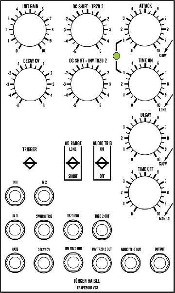
Too many irons in the fire! We finally put together something we both like. It doesn't conform to the usual MOTM conventions, which will probably tick some people off. My collaborator convinced me that it would be better to put the inputs on the left and the outputs on the right.
I still have a little bit of tweaking to do on the horizontal spacing, but it's very close to what we'll screenprint. |
I really like the panel design for your dual trapezoid. Great work! |
|
|
Back to top
|
|
|
numbertalk
Joined: May 05, 2008
Posts: 992
Location: Austin, TX
Audio files: 5
|
| Posted: Tue Dec 07, 2010 5:50 pm Post subject:
|
|
|
2 more corrections for the BOM:
There should be 2 470n caps
There should be 2 BC560Cs and 4 BC550Cs (not counting the matched pair that can be replaced by an IC) |
|
|
Back to top
|
|
|
wjhall
Joined: Dec 09, 2010
Posts: 1
Location: NJ-USA
|
|
|
Back to top
|
|
|
bennethos

Joined: Apr 18, 2009
Posts: 31
Location: Belgium
|
|
|
Back to top
|
|
|
jhaible
Joined: May 25, 2007
Posts: 2014
Location: Germany
Audio files: 24
|
| Posted: Tue Feb 08, 2011 6:14 am Post subject:
|
|
|
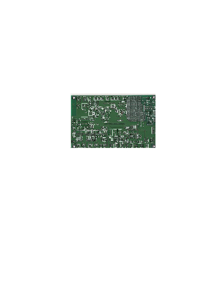
My Prototype PCB of the trapezoid will be on ebay tonight, starting at 20:00 MEZ.
JH.
_________________
"I tell you the truth, if anyone says to this mountain, 'Go, throw yourself into the sea,' and does not doubt in his heart but believes that what he says will happen, it will be done for him. Therefore I tell you, whatever you ask for in prayer, believe that you have received it, and it will be yours." (Mk 11,23f) |
|
|
Back to top
|
|
|
MR-808
Joined: Sep 30, 2010
Posts: 28
Location: Portland, OR
|
| Posted: Tue Jun 28, 2011 1:07 pm Post subject:
|
|
|
I'm finally getting around to building my JH Trapezoid VCAs, and now that the pcbs are stuffed and missing some parts, I have a few corrections to Bill & Will's BOM (dated 12/9/10). To wit:
Resistors - (3, not 1) 220 Ohm, (5) 470 ohm, (1) 620 Ohm, (1, not 6) 470kOhm.
Capacitors - (9, not 8) 100nF.
Diodes - (11, not 10) 1N4148.
Transistors - (1) 2N5461.
That's it AFAIK. Can't wait to get them wired up and hear how they work! |
|
|
Back to top
|
|
|
emdot_ambient
Joined: Nov 22, 2009
Posts: 667
Location: Frederick, MD
|
| Posted: Wed Jun 29, 2011 7:47 am Post subject:
|
|
|
Thanks for the update...I've got 2 of them almost built...not sure where I left off, though. My backlog pile is rapidly becoming my "almost completed PCB" pile. After a while I kind of lost track what's missing from what. 
_________________
Looking for a certain ratio since 1978 |
|
|
Back to top
|
|
|
MR-808
Joined: Sep 30, 2010
Posts: 28
Location: Portland, OR
|
| Posted: Wed Jun 29, 2011 10:32 pm Post subject:
|
|
|
| LOLZ. My "almost completed PCB" pile is growing, too. I've got a "pick-up sheet" where I track what's missing, because I always seem to miss something. |
|
|
Back to top
|
|
|
Davedatt
Joined: Jan 12, 2012
Posts: 7
Location: Portland OR.
|
| Posted: Thu Jan 12, 2012 10:42 pm Post subject:
|
|
|
Hey there,
I am debugging the 2nd JH board for our Dual Panel TG. I have reached a point where I am looking for the final bug that is so slight that despite the fact I have it's twin working perfectly now I am at my wits end.
The problem is simple. At maximum off time I still get the unit self cycling about every 7 seconds.
All controls work as its twin.
Maximum cycle times are identical.
No DC offsets on the outputs.
Just wondering if anyone else has seen this. Yes I am and have gone thru the tedious job of checking resister and cap values. I am wondering if I have a tolerance issue with a component.
Sigh....
Dave |
|
|
Back to top
|
|
|
Davedatt
Joined: Jan 12, 2012
Posts: 7
Location: Portland OR.
|
| Posted: Fri Jan 13, 2012 12:47 pm Post subject:
|
|
|
Has anyone measured the maximum cycle time or frequency of the trapezoid generator? Or measured stability of the device?
Dave |
|
|
Back to top
|
|
|
MR-808
Joined: Sep 30, 2010
Posts: 28
Location: Portland, OR
|
| Posted: Wed Jan 18, 2012 5:19 pm Post subject:
|
|
|
I don't think anybody has actually completed theirs yet. ;)
NOTE: Dave and I have been working on our Trapezoid panels together. I am posting debug comments here in case they help someone else.
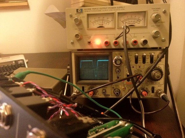
In Jürgen's video: http://www.youtube.com/watch?v=KzcAhTQQx3s , he demonstrates the trapezoid being off. So we definitely have a problem.
I also tried to determine the maximum frequency. I couldn't get a good audio signal from the video, so I tuned a synth by ear to match and measured it on the scope. It seems like Jürgen's trapezoid will go up to ~125Hz; ours does about 89Hz. Looking at the images, the attack slope isn't as steep on ours - that could be a clue.
Did using a lower current LED affect the max frequency of yours?
Hmmm...
PS Jürgen, I miss you, and not just because I could use your help debugging this thing. :( |
|
|
Back to top
|
|
|
Davedatt
Joined: Jan 12, 2012
Posts: 7
Location: Portland OR.
|
|
|
Back to top
|
|
|
emdot_ambient
Joined: Nov 22, 2009
Posts: 667
Location: Frederick, MD
|
|
|
Back to top
|
|
|
MR-808
Joined: Sep 30, 2010
Posts: 28
Location: Portland, OR
|
| Posted: Fri Jan 20, 2012 3:32 am Post subject:
|
|
|
I'm not sure if I fixed it, or if I just applied a band-aid to cover up a build error, but both of mine appear to be working normally. :)
The first clue was when a 'scope probe applied to what I call the "trigger node" (where R19 & R20 meet) caused the occasional trigger to completely go away. At first I thought it might be the capacitance of the probe & cable. Now I'm pretty sure it was the paralleled resistance of the probe dropping the resistance slightly. I replaced R19 with a 1M trimpot and dialed it down to ~950k, and that did the trick! Now it's possible to turn the triggering off completely by turning the OFF TIME all the way down.
I don't think it had any other effect on the circuit - it seems to be able to retrigger just as fast as before the mod.
I'm curious to hear if anybody else has a retriggering problem. Did we make a mistake? Are there parts out of tolerance (resistors are 1%, caps 5%, pots 5%)? Is it just a quirky circuit?
It is odd that Dave had a 4558 and 741 blow. And we both had several bypass caps blow (might just be a bad batch from Jameco - they no longer stock those, I see). I'm going to burn mine in for several hours before I finish assembly. Unless I encounter some other problem, though, I'm going to call it good for now.
Pictures when I'm done testing! |
|
|
Back to top
|
|
|
v-un-v
Janitor


Joined: May 16, 2005
Posts: 8932
Location: Birmingham, England, UK
Audio files: 11
G2 patch files: 1
|
| Posted: Fri Jan 20, 2012 4:03 am Post subject:
|
|
|
Does anyone know what will come of the PCB for the Trapezoid? I was saving for one, and then we lost Jurgen
_________________
ACHTUNG!
ALLES TURISTEN UND NONTEKNISCHEN LOOKENPEEPERS!
DAS KOMPUTERMASCHINE IST NICHT FÜR DER GEFINGERPOKEN UND MITTENGRABEN! ODERWISE IST EASY TO SCHNAPPEN DER SPRINGENWERK, BLOWENFUSEN UND POPPENCORKEN MIT SPITZENSPARKSEN.
IST NICHT FÜR GEWERKEN BEI DUMMKOPFEN. DER RUBBERNECKEN SIGHTSEEREN KEEPEN DAS COTTONPICKEN HÄNDER IN DAS POCKETS MUSS.
ZO RELAXEN UND WATSCHEN DER BLINKENLICHTEN. |
|
|
Back to top
|
|
|
emdot_ambient
Joined: Nov 22, 2009
Posts: 667
Location: Frederick, MD
|
| Posted: Fri Jan 20, 2012 2:07 pm Post subject:
|
|
|
I haven't seen anything lately on what's happening with JH's estate. I suspect it will take a while before they figure out what to do with his electronics stuff.
_________________
Looking for a certain ratio since 1978 |
|
|
Back to top
|
|
|
Davedatt
Joined: Jan 12, 2012
Posts: 7
Location: Portland OR.
|
Posted: Sun Jan 22, 2012 1:27 am Post subject:
Subject description: My Build. |
|
|
Now works great. Same thing as Mr. 808. 1 meg trim in place of R19, dialed down slightly. I did replace my LED's with 2ma LEDs as well. I suspect our origional or power up failures are related to the original 30ma LED's placing a transiant on the PS busses. Possibly responsible for the bypass cap problems. Little bit concerned about the soft off time, after about 3:00 o'clock I am in a manual time mode. Or at least I got tired of waiting for a re-trigger.
dave |
|
|
Back to top
|
|
|
|

 Forum index » DIY Hardware and Software » Jürgen Haible designs