| Author |
Message |
marvkaye
Joined: Mar 14, 2011
Posts: 225
Location: Fla
|
 Posted: Fri Aug 26, 2011 5:14 pm Post subject: Posted: Fri Aug 26, 2011 5:14 pm Post subject:
|
  |
|
Great ideas, Tim. I've suffixed the LFX with an "r1" and added it and the date to the silkscreen. I've already placed a MiniBoard Pro order for these, should see them on Monday. I'll put up photos as soon I get one populated.
If you'd be so kind to post the LED driver addition I'll bet it could be added to the existing board without growing its size. Personally, I don't have a problem adding a little daughterboard (if necessary) to add functionality.
<marv> |
|
|
Back to top
|
|
 |
bubzy

Joined: Oct 27, 2010
Posts: 594
Location: United Kingdom
Audio files: 64
|
| Posted: Sat Aug 27, 2011 12:08 am Post subject:
|
|
|
| added the text and transistor to my layout, have etched the board just now, gotta wait for my wife to wake up before i drill it though :p results later ......... |
|
|
Back to top
|
|
|
bubzy
Joined: Oct 27, 2010
Posts: 594
Location: United Kingdom
Audio files: 64
|
| Posted: Sat Aug 27, 2011 10:23 am Post subject:
|
|
|
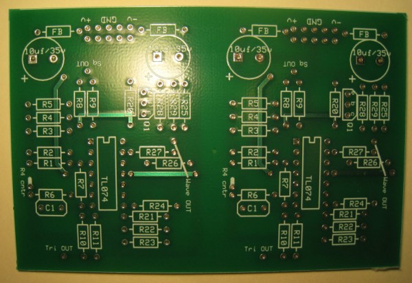
working  pcb layout confirmed :p pcb layout confirmed :p |
|
|
Back to top
|
|
|
marvkaye
Joined: Mar 14, 2011
Posts: 225
Location: Fla
|
| Posted: Sat Aug 27, 2011 11:33 am Post subject:
|
|
|
| bubzy wrote: | | working pcb layout confirmed :p |
Very cool, congratulations and well done. Care to share your update with the LED driver?? |
|
|
Back to top
|
|
|
v-un-v
Janitor


Joined: May 16, 2005
Posts: 8932
Location: Birmingham, England, UK
Audio files: 11
G2 patch files: 1
|
| Posted: Sat Aug 27, 2011 11:59 am Post subject:
|
|
|
| tokyomatik wrote: | i already went to that web site but i use a mac, i didn't found a version for osx  |
It's worth getting Fusion or Parallels for this. I know it's a pain, but it's a little price to pay for progress. Swings and roundabouts really. Because you have the Mac, you save on no having to buy all that stupid extra software to keep the damn PC in check. Just update everything initially, do a clone, and trash the bugger when it goes wrong, replacing it with a clone of the clone later!
Great LFO Tim!
_________________
ACHTUNG!
ALLES TURISTEN UND NONTEKNISCHEN LOOKENPEEPERS!
DAS KOMPUTERMASCHINE IST NICHT FÜR DER GEFINGERPOKEN UND MITTENGRABEN! ODERWISE IST EASY TO SCHNAPPEN DER SPRINGENWERK, BLOWENFUSEN UND POPPENCORKEN MIT SPITZENSPARKSEN.
IST NICHT FÜR GEWERKEN BEI DUMMKOPFEN. DER RUBBERNECKEN SIGHTSEEREN KEEPEN DAS COTTONPICKEN HÄNDER IN DAS POCKETS MUSS.
ZO RELAXEN UND WATSCHEN DER BLINKENLICHTEN. |
|
|
Back to top
|
|
|
Dougster

Joined: Sep 20, 2005
Posts: 272
Location: Tucson, AZ, USA
|
| Posted: Sat Aug 27, 2011 12:07 pm Post subject:
|
|
|
/me posts obligatory complaint about software not being available under Linux...
(Which is why I use Eagle...)
_________________
Once you start down the modular path, forever will it dominate your destiny!
Every DIY person should own a copy of Electronotes: http://electronotes.netfirms.com
Blue LEDs are evil. |
|
|
Back to top
|
|
|
Tim Servo

Joined: Jul 16, 2006
Posts: 924
Location: Silicon Valley
Audio files: 11
|
Posted: Sun Aug 28, 2011 12:35 pm Post subject:
The LFX experimental LFO (8K LFO and Weird Waveshapers)
Subject description: R 02 schematic with new R5 value |
|
|
Hey Everyone,
One small change to note. R5 should be 220 Ohms, not 470 Ohms as I originally listed. I've updated the schematic on the first page, so that is correct now. With R5 at 470 Ohms, you'll only get a range of 4,200:1, but with R5 at 220 Ohms, you'll get the full range (about 8,800:1). Sorry for the error, and thanks again to Ian Fritz for letting me know. If you've already installed R5 and don't want to pull it out, you could just install another 470 Ohm resistor in parallel. The resulting resistance will be roughly 230 Ohms, which is definitely close enough.
Cheers,
Tim (one small change) Servo |
|
|
Back to top
|
|
|
marvkaye
Joined: Mar 14, 2011
Posts: 225
Location: Fla
|
|
|
Back to top
|
|
|
Tim Servo
Joined: Jul 16, 2006
Posts: 924
Location: Silicon Valley
Audio files: 11
|
| Posted: Mon Aug 29, 2011 7:08 pm Post subject:
The LFX experimental LFO (8K LFO and Weird Waveshapers) |
|
|
Hey Marv,
Looks nice! A couple of thoughts on PCBs (these are just some things I do on my own / Magic Smoke PCBs)
1) Include the board name, and a date or revision number so you know what the board is and what schemo you used for it.
2) On the part designators (R1, U3, etc.), I always try to move them off to one side so that they're still visible when the part is in place. Makes troubleshooting or modding quicker and easier. You can't always do this on really cramped boards, but one most of mine I've been able to do it.
3) If possible, try to keep all similar parts pointing in the same direction. In other words, all ICs should point the same direction. I also try to keep all resistors in the same orientation. It generally makes assembly easier and makes the board look cleaner. This is a must for boards that are going to be automated, although that's something I've never had to worry about (although I do have a project coming up ...)
4) Whenever possible, traces on one side of the board should be at a right angle to traces on the other side. This minimizes interference, and even though that's not going to be a problem on an LFO board, it is a good habbit to get into.
For layout software, I've had really good luck with KiCAD (and it's free / open source).
Let us know how the LFX boards work out!
Cheers,
Tim (has plenty of bad habbits too) Servo |
|
|
Back to top
|
|
|
marvkaye
Joined: Mar 14, 2011
Posts: 225
Location: Fla
|
| Posted: Mon Aug 29, 2011 7:45 pm Post subject:
|
|
|
HI Tim,
Thanks for all the great pointers. If I ever manage to actually come up with my own PCB design I'll try to keep them in mind. It was actually bubzy who did all the heavy lifting with this one, I just made a few very minor changes and sent ExpressPCB money 
I'll probably cut small stencils for them and airbrush the name of the board and revision down the center... I figured I'd keep them together and layout a MOTM style front panel that accommodates the pair.
Did you ever come up with the LED driver for this? MFOS Ray has a simple one that takes a couple resistors and a 2n3904 (on his Synth DIY page under the "Hot tips" menu item) but I don't know if it's appropriate to this application or even where it would tie into the circuit. Just curious....
<marv> |
|
|
Back to top
|
|
|
Tim Servo
Joined: Jul 16, 2006
Posts: 924
Location: Silicon Valley
Audio files: 11
|
| Posted: Mon Aug 29, 2011 10:07 pm Post subject:
The LFX experimental LFO (8K LFO and Weird Waveshapers) |
|
|
Hi Marv,
For marking the boards, you might want to also consider a fine-tip permanent marker, or even a paint marker (don't know if those come in a fine tip).
As far as an LED driver, the transistor driver on Ray's site is an excellent, and very simple solution. I have some slight enhancements on that, but that original design is the simplest. You can hook it up to any of the waveform outputs - the buffer will pull very little current from the output, so the output can still drive lots of mod inputs.
Tim (the original, and the simplest) Servo |
|
|
Back to top
|
|
|
bubzy
Joined: Oct 27, 2010
Posts: 594
Location: United Kingdom
Audio files: 64
|
|
|
Back to top
|
|
|
marvkaye
Joined: Mar 14, 2011
Posts: 225
Location: Fla
|
| Posted: Tue Aug 30, 2011 5:26 am Post subject:
|
|
|
| Quote: | | sorry its been such a while, been very busy |
Life beyond e-m.com?.?.? Whoda thunk it? 
Not a problem. The LED schematic you shared is very similar to the one on MFOS... I'll do the math for the LEDs I'm planning on using and modify the circuit accordingly. Thanks for sharing it.
Can't wait to open up your new zipfile, anxious to see your LED implentation... no time now, but later. Life beyond e-m.com, doncha know?? 
<marv> |
|
|
Back to top
|
|
|
Tim Servo
Joined: Jul 16, 2006
Posts: 924
Location: Silicon Valley
Audio files: 11
|
| Posted: Tue Sep 06, 2011 5:24 pm Post subject:
The LFX experimental LFO (8K LFO and Weird Waveshapers) |
|
|
Hi All,
I just posted a handul of different LED driver circuits at
http://www.electro-music.com/forum/topic-49449.html
I'll post more as I have time, but there are a few there to get you started. I use the "Bipolar Driver with Adjustable Bias" for the output of my LFX and it really works nicely.
Tim (head towards the blinky light) Servo |
|
|
Back to top
|
|
|
oculus
Joined: Oct 30, 2011
Posts: 35
Location: Iceland, Reykjavik
|
| Posted: Mon Jul 22, 2013 7:46 pm Post subject:
|
|
|
Congrats and thanks for sharing this Tim
this LFO sounds very interesting,
i´ll definetly try this one out.
this would be amazing with a retrigger option,
to be able to kind of sync it to the tempo of the song one would be working on.
do you think this could be possible by using a fet transistor ? or some other way? |
|
|
Back to top
|
|
|
Tim Servo
Joined: Jul 16, 2006
Posts: 924
Location: Silicon Valley
Audio files: 11
|
|
|
Back to top
|
|
|
feggster
Joined: Sep 12, 2011
Posts: 52
Location: uk
|
| Posted: Wed Jul 24, 2013 1:32 am Post subject:
|
|
|
| bubzy wrote: | | working pcb layout confirmed :p |
hi, looking at the pcb..where do the pots connect? do they use the same numbering as the schematic? |
|
|
Back to top
|
|
|
oculus
Joined: Oct 30, 2011
Posts: 35
Location: Iceland, Reykjavik
|
| Posted: Wed Jul 24, 2013 8:18 am Post subject:
Re: The LFX experimental LFO (8K LFO and Weird Waveshapers) |
|
|
| Tim Servo wrote: | Hi Oc,
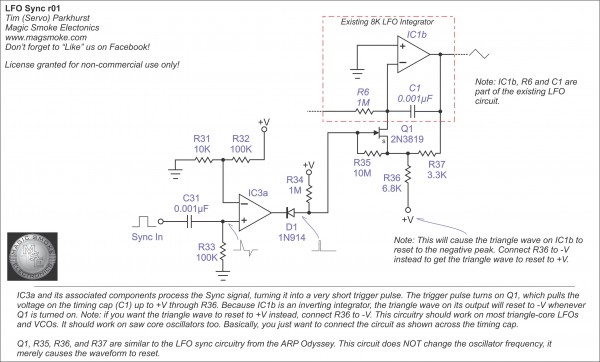
Yes, it's pretty easy to set up sync on this (or most other) LFOs by using an FET or an analog switch to change the charge on the timing cap. You can set up the circuit to pull the cap up to V+ or down to V-. In most triangle core oscillators, the integrator is inverting, so this means that pulling the timing cap up to V+ means the output triangle will be reset to V-. By the same token, pulling the cap down to V- means that the output wave will reset to its positive peak. It just depends on what behavior you prefer (or you could even put in a switch). The circuit below has already been posted on the Magic Smoke Facebook page (that's the place to go if you want to see this stuff a little sooner).
Tim (peaky!) Servo |
Nice thank you so much, can´t wait getting back home from the countryside to try this circuit out. |
|
|
Back to top
|
|
|
diablojoy

Joined: Sep 07, 2008
Posts: 809
Location: melbourne australia
Audio files: 11
|
| Posted: Wed Jul 24, 2013 7:27 pm Post subject:
|
|
|
Tim is there a reason for not pulling the intergrator cap to 0V ?
instead of the negative or positive rail
resetting the wave to 0V seems more intuitive to me
_________________
In an infinite universe one might very well
ask where the hell am I
oh yeah thats right the land of OZ
as good an answer as any |
|
|
Back to top
|
|
|
Tim Servo
Joined: Jul 16, 2006
Posts: 924
Location: Silicon Valley
Audio files: 11
|
Posted: Wed Jul 24, 2013 10:29 pm Post subject:
The LFX experimental LFO (8K LFO and Weird Waveshapers)
Subject description: A question of resets... |
|
|
Hey DJ,
In this design, you can reset the cap to 0V by connecting the 6.8K resistor to 0V. However, if you pull the cap to 0V, the output won't consistently reset. If the LFO wave was on the down slope, a reset to 0V will make the output start at 0V and head negative. On the other hand, if the LFO wave was on an upward slope, the reset will set the output to 0 and the it will start up. Resetting the LFO wave to the negative (or positive) peak means that the output behaves exactly the same way on every reset, regardless of where the LFO wave was when the sync pulse hits.
Tim (resetting it to 0K?) Servo |
|
|
Back to top
|
|
|
bubzy
Joined: Oct 27, 2010
Posts: 594
Location: United Kingdom
Audio files: 64
|
| Posted: Thu Jul 25, 2013 4:11 am Post subject:
|
|
|
| feggster wrote: |
hi, looking at the pcb..where do the pots connect? do they use the same numbering as the schematic? |
yep
_________________
_Richard_ |
|
|
Back to top
|
|
|
feggster
Joined: Sep 12, 2011
Posts: 52
Location: uk
|
| Posted: Thu Jul 25, 2013 2:17 pm Post subject:
|
|
|
| bubzy wrote: | | feggster wrote: |
hi, looking at the pcb..where do the pots connect? do they use the same numbering as the schematic? |
yep |
thanks, another great schematic and pcb to add to my to do list |
|
|
Back to top
|
|
|
diablojoy
Joined: Sep 07, 2008
Posts: 809
Location: melbourne australia
Audio files: 11
|
| Posted: Thu Jul 25, 2013 3:29 pm Post subject:
|
|
|
| Quote: | | In this design, you can reset the cap to 0V by connecting the 6.8K resistor to 0V. However, if you pull the cap to 0V, the output won't consistently reset. If the LFO wave was on the down slope, a reset to 0V will make the output start at 0V and head negative. On the other hand, if the LFO wave was on an upward slope, the reset will set the output to 0 and the it will start up. |
Thanks Tim
makes perfect sense.
I seem to remember seeing something along similar lines on the time machine schematic using a DG chip for resetting the LFO /EG to a known point and forcing a particular direction, would have to look it up again though to be sure.
_________________
In an infinite universe one might very well
ask where the hell am I
oh yeah thats right the land of OZ
as good an answer as any |
|
|
Back to top
|
|
|
bubzy
Joined: Oct 27, 2010
Posts: 594
Location: United Kingdom
Audio files: 64
|
|
|
Back to top
|
|
|
isak

Joined: Dec 13, 2009
Posts: 847
Location: Israel
Audio files: 18
|
| Posted: Thu Sep 26, 2013 10:13 am Post subject:
|
|
|
Hi Tim and Guys.
just wanted to make sure that the scheme that open this post is the last updated scheme of the 8k LFO, i'm asking cause i seen few schemes of the 8k in the forum
cheers,
Isak E.
_________________
http://www.myspace.com/mgmtrance |
|
|
Back to top
|
|
|
|

 Forum index » DIY Hardware and Software