| Author |
Message |
frijitz
Joined: May 04, 2007
Posts: 1734
Location: NM USA
Audio files: 54
|
 Posted: Tue Jan 10, 2012 10:36 am Post subject: Posted: Tue Jan 10, 2012 10:36 am Post subject:
|
  |
|
| asterisk wrote: | | any tips about how to troubleshoot this circuit so i can get it to work? i dont even know where to start or what problems to look for. |
Any circuit that's a loop is hard to troubleshoot, since the problem cousd be anywhere. I'd start by making sure the pots are wired correctly. That's the easiest place to get confused.
The previous problem with a cap was not actually a bug, just that a trace runs between the legs of the cap and you can get a short there.
Ian |
|
|
Back to top
|
|
 |
asterisk
Joined: Sep 17, 2011
Posts: 17
Location: burlington, VT
|
| Posted: Tue Jan 10, 2012 9:49 pm Post subject:
|
|
|
ok ill start by checking out my pot wiring.
couple of clarifications there:
if im looking at the dual gang 1M pot from the top (not the backside), the solder lugs are 1-2-3 on the top row and 4-5-6 on the bottom row right?
my other 2 pots are multiturn pots and the lugs are labelled 1-2-3, so those are easy enough.
i did make the connection from lug 4 of the rate pot to lug 1 of the damping pot. and the input jack is soldered to lug 1 of the drive pot.
ill double check that all of my pot wiring is going to to appropriate places on the PCB.
whats the best way to ground all of the jacks? wire the grounds on all 4 of them together and then wire that to a ground point on the PCB?
ill check voltages to my ICs. they should be +/- 12v at the appropriate pins right? and ill check all of my resistor / cap values, make sure i didnt put something in the wrong place.
ill report back, hopefully i can get this thing working! |
|
|
Back to top
|
|
|
asterisk
Joined: Sep 17, 2011
Posts: 17
Location: burlington, VT
|
| Posted: Wed Jan 11, 2012 1:39 am Post subject:
|
|
|
YAY! i fixed it and its working.
i made a stupid beginner's mistake. i had wired up the power header incorrectly the first time (but it miraculously didn't fry the board!).
fixed up the power header/connector and its working great.
was getting some amazing chaos patterns using the outputs going to 1 VCO and 1 VCF. with a modulated / random LFO going into the input.
ill try to record this patch tomorrow or soon and post a clip. |
|
|
Back to top
|
|
|
asterisk
Joined: Sep 17, 2011
Posts: 17
Location: burlington, VT
|
| Posted: Fri Jan 13, 2012 12:22 am Post subject:
|
|
|
here is a quick test / demo of my Double Well Chaos module for eurorack. everything seems to be working well. check the soundcloud page for more info on the patch. i was wiggling the knobs in realtime and the drive LFO was changing frequency randomly.
http://soundcloud.com/greg-davis/double-well-chaos-test-011312 |
|
|
Back to top
|
|
|
frijitz
Joined: May 04, 2007
Posts: 1734
Location: NM USA
Audio files: 54
|
| Posted: Fri Jan 13, 2012 12:23 pm Post subject:
|
|
|
| asterisk wrote: | here is a quick test / demo of my Double Well Chaos module for eurorack. everything seems to be working well. check the soundcloud page for more info on the patch. i was wiggling the knobs in realtime and the drive LFO was changing frequency randomly.
http://soundcloud.com/greg-davis/double-well-chaos-test-011312 |
Great! Sounds like it's working properly.
Ian |
|
|
Back to top
|
|
|
elmegil

Joined: Mar 20, 2012
Posts: 2177
Location: Chicago
Audio files: 16
|
| Posted: Sun Oct 21, 2012 7:00 pm Post subject:
Zener Values |
|
|
I see from earlier discussion that 4.7's can be used in place of 4.3's, it just changes the overall shape.
How far does that go before it's unusable? I thought I had 4.3's on hand, but have found out I don't, they're not available locally, and I'm not much inclined to order just 2 zeners from Mouser given their shipping costs  . I do have 5.1's.... . I do have 5.1's....
I spose I should just breadboard it.... |
|
|
Back to top
|
|
|
frijitz
Joined: May 04, 2007
Posts: 1734
Location: NM USA
Audio files: 54
|
| Posted: Sun Oct 21, 2012 8:50 pm Post subject:
Re: Zener Values |
|
|
| elmegil wrote: | I see from earlier discussion that 4.7's can be used in place of 4.3's, it just changes the overall shape.
How far does that go before it's unusable? I thought I had 4.3's on hand, but have found out I don't, they're not available locally, and I'm not much inclined to order just 2 zeners from Mouser given their shipping costs . I do have 5.1's.... |
I'm not sure which circuit you are refering to. I would say tack the 5.1's in temporarily and see how it works. Then replace them the next time you are putting in a parts order.
Ian |
|
|
Back to top
|
|
|
elmegil
Joined: Mar 20, 2012
Posts: 2177
Location: Chicago
Audio files: 16
|
| Posted: Sun Oct 21, 2012 8:56 pm Post subject:
|
|
|
| Sorry it was the double well chaos circuit/PCB from '07. I'll give it a shot, good point about replacing them. |
|
|
Back to top
|
|
|
prgdeltablues
Joined: Sep 25, 2006
Posts: 222
Location: UK
Audio files: 12
|
| Posted: Mon Oct 22, 2012 4:10 am Post subject:
|
|
|
Or tack a diode in series after the zener - 0.6V voltage drop - 5.1 down to 4.5.
Peter |
|
|
Back to top
|
|
|
frijitz
Joined: May 04, 2007
Posts: 1734
Location: NM USA
Audio files: 54
|
| Posted: Mon Oct 22, 2012 7:25 am Post subject:
|
|
|
| prgdeltablues wrote: | Or tack a diode in series after the zener - 0.6V voltage drop - 5.1 down to 4.5.
Peter |
Wouldn't that add 0.6 V?
Ian |
|
|
Back to top
|
|
|
prgdeltablues
Joined: Sep 25, 2006
Posts: 222
Location: UK
Audio files: 12
|
| Posted: Mon Oct 22, 2012 7:48 am Post subject:
|
|
|
Sorry, I responded without reading the schematic. Please ignore my message.
Peter |
|
|
Back to top
|
|
|
elmegil
Joined: Mar 20, 2012
Posts: 2177
Location: Chicago
Audio files: 16
|
|
|
Back to top
|
|
|
frijitz
Joined: May 04, 2007
Posts: 1734
Location: NM USA
Audio files: 54
|
| Posted: Tue Oct 23, 2012 8:22 am Post subject:
|
|
|
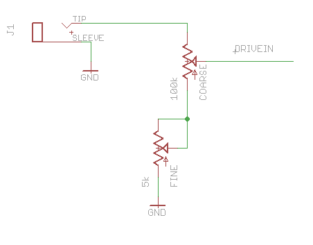
| elmegil wrote: | | I *think* it means to wire it like the attached picture. Is that correct? |
Yep, that's it. 
Ian |
|
|
Back to top
|
|
|
frequencycentral

Joined: May 25, 2008
Posts: 186
Location: UK
|
| Posted: Tue Oct 23, 2012 11:24 am Post subject:
|
|
|
| frijitz wrote: | | asterisk wrote: | here is a quick test / demo of my Double Well Chaos module for eurorack. everything seems to be working well. check the soundcloud page for more info on the patch. i was wiggling the knobs in realtime and the drive LFO was changing frequency randomly.
http://soundcloud.com/greg-davis/double-well-chaos-test-011312 |
Great! Sounds like it's working properly.
Ian |
Only here...
I love it that that is the sound of something working properly. 
_________________
http://www.frequencycentral.co.uk/ |
|
|
Back to top
|
|
|
frequencycentral
Joined: May 25, 2008
Posts: 186
Location: UK
|
|
|
Back to top
|
|
|
AlanP
Joined: Mar 11, 2014
Posts: 746
Location: New Zealand
Audio files: 41
|
| Posted: Sat Feb 07, 2015 12:18 pm Post subject:
|
|
|
| Are any mods needed to run the Jerkster or EZ Chaos on +/- 12V Eurorack? |
|
|
Back to top
|
|
|
drapdap

Joined: Oct 11, 2004
Posts: 204
Location: London
Audio files: 1
G2 patch files: 1
|
| Posted: Mon Feb 09, 2015 11:45 am Post subject:
|
|
|
on the jerkster it's just the four resistors for the ota, 22k on 12volts, 27k on 15. im not shure about the dweller, wanted to check anyways...
but the first jerkster i've built are still run from 15 and have 22k, so even that works. for a while probably. |
|
|
Back to top
|
|
|
wackelpeter
Joined: May 05, 2013
Posts: 461
Location: germany
Audio files: 10
|
|
|
Back to top
|
|
|
frijitz
Joined: May 04, 2007
Posts: 1734
Location: NM USA
Audio files: 54
|
| Posted: Sun Feb 22, 2015 6:07 pm Post subject:
|
|
|
| AlanP wrote: | | Are any mods needed to run the Jerkster or EZ Chaos on +/- 12V Eurorack? |
No, they are designed for 12V operation.
Ian |
|
|
Back to top
|
|
|
frijitz
Joined: May 04, 2007
Posts: 1734
Location: NM USA
Audio files: 54
|
| Posted: Sun Feb 22, 2015 6:31 pm Post subject:
|
|
|
| wackelpeter wrote: | | The main reason posting here is i wanted to ask if someone have an idea how to Limit the otuputs of the jerkster around +/-5V with maybe 1-2 Volt more not being that critical? |
It's the nature of chaos that signal amplitudes vary over a wide range. You can reduce the overall range by adding a resistor between pins 4 and 11 of U3. This should be a fairly large value; start with 3.3MOhm or so and experiment until you get what you want. Yes, the output levels go beyond the 5V standard, but I haven't seen any situation where this is a problem. However, if they are always very large, then there may be some issue with your build.
| Quote: | | also i'm trying to get the range behaviour a bit more controllabel as it drifts very fast from very slow to Audio range oscillations... means i have not much control over the lower regions... just a simple smaller pot in series with the rate pot? |
Yes, exactly (as suggested in the docs).
Ian |
|
|
Back to top
|
|
|
wackelpeter
Joined: May 05, 2013
Posts: 461
Location: germany
Audio files: 10
|
| Posted: Mon Feb 23, 2015 9:21 am Post subject:
|
|
|
Thanks Ian, i'll try this out and Report if it turned out successful for me or not...
P.S. regarding the high Output values... they'll grow from Little (less than 5V) to nearly the value of the power rails...
Except when i turn the gain fully down or was it up than on 1 or 2 of them the Output stays at power rail value...
i already thought about adding a resistor from outout to ground to lower the Amplitude a bit and passing the Output Signal through an cap to block DC voltage... that seem to work on one of the Outputs so far but haven't checked what it caused to the other Outputs as they interact with each other...
_________________
https://soundcloud.com/bastian-j |
|
|
Back to top
|
|
|
wackelpeter
Joined: May 05, 2013
Posts: 461
Location: germany
Audio files: 10
|
| Posted: Tue Feb 24, 2015 10:54 am Post subject:
|
|
|
Ian followed your advice and that did the trick... thanks...
recorded a short sample using your jerkster and tgtsh circuits...
jerkster 2 Outputs going into the tgtsh Signal Inputs Trigger gate out of both to Env.Generators...
LFO and Psycho LFo to S&H Inputs... Those Outputs into V/oct Inputs via attentuators of 2 TH 555 VCO's and those saw Outputs via Yusynth Steiner and EMS VCF into a VCA each fed by the Envelopes... a bit of delay and that's it...
| Description: |
|

Download |
| Filename: |
tgtsgjerkster1_0.mp3 |
| Filesize: |
535.34 KB |
| Downloaded: |
1470 Time(s) |
| Description: |
| slighlty the same as above but both VCO modulating each other and jerkster controlled by lfo |
|
Download |
| Filename: |
tgtsgjerkster2_1.mp3 |
| Filesize: |
703.3 KB |
| Downloaded: |
1483 Time(s) |
_________________
https://soundcloud.com/bastian-j
Last edited by wackelpeter on Tue Feb 24, 2015 11:48 am; edited 1 time in total |
|
|
Back to top
|
|
|
frijitz
Joined: May 04, 2007
Posts: 1734
Location: NM USA
Audio files: 54
|
| Posted: Tue Feb 24, 2015 11:35 am Post subject:
|
|
|
| wackelpeter wrote: | Ian followed your advice and that did the trick... thanks...
recorded a short sample using your jerkster and tgtsh circuits...
jerkster 2 Outputs going into the tgtsh Signal Inputs Trigger gate out of both to Env.Generators...
LFO and Psycho LFo to S&H Inputs... Those Outputs into V/oct Inputs via attentuators of 2 TH 555 VCO's and those saw Outputs via Yusynth Steiner and EMS VCF into a VCA each fed by the Envelopes... a bit of delay and that's it... |
Great! Glad it was easy to tame. Your demo really brings out the "always the same but always different" property of chaos.
Ian |
|
|
Back to top
|
|
|
wackelpeter
Joined: May 05, 2013
Posts: 461
Location: germany
Audio files: 10
|
| Posted: Tue Feb 24, 2015 11:58 am Post subject:
|
|
|
yep it's a nice circuit... thanks a lot for sharing this with us...
Is it also working correct in that manner that one Output is centered around gnd whilst the others are also but one with an slightly (1-2V) positive and the other with an slightly negative Offset? Or has this something to do with the 220R resistors going to the LM13700 in case they are not matched properly? i'm not sure respectively can't remember if i put attention to this whilst soldering....
_________________
https://soundcloud.com/bastian-j |
|
|
Back to top
|
|
|
frijitz
Joined: May 04, 2007
Posts: 1734
Location: NM USA
Audio files: 54
|
| Posted: Fri Feb 27, 2015 7:28 pm Post subject:
|
|
|
| wackelpeter wrote: | yep it's a nice circuit... thanks a lot for sharing this with us...
Is it also working correct in that manner that one Output is centered around gnd whilst the others are also but one with an slightly (1-2V) positive and the other with an slightly negative Offset? Or has this something to do with the 220R resistors going to the LM13700 in case they are not matched properly? i'm not sure respectively can't remember if i put attention to this whilst soldering.... |
The offsets are normal. You might want to look at some typical chaos examples at my website to get a better feel for this.
Ian |
|
|
Back to top
|
|
|
|

 Forum index » DIY Hardware and Software