| Author |
Message |
Uncle Krunkus
Moderator

Joined: Jul 11, 2005
Posts: 4761
Location: Sydney, Australia
Audio files: 52
G2 patch files: 1
|
 Posted: Sat Jul 28, 2012 4:42 am Post subject:
Nexus 1 Posted: Sat Jul 28, 2012 4:42 am Post subject:
Nexus 1
Subject description: Major samples - Use with credit please |
  |
|
Okay,
These three schemes show what I already have to work with.
It's all laid out on piece of stripboard, (which I'll take a pic of later).
I designed and laid it out around 1995. No software to design or test on then. I actually find it amazing that it worked quite well. Straight off the bat.
Even relative newcomers to SDIY should be able to see quite a few alarming errors on this schem. But it would be good if we can find them all, don't ya reckon? It's transcribed exactly as the stripboard is already built. And it works,....kinda,... But if I fix the errors on the board as we find them, then it will end up heaps better. I'm already quite certain I can cut the current draw by 100:1! 
It is not yet a Lunetta (technically) as it doesn't make a sound. Not yet. 
Half the stripboard is empty.
The challenge is to find a way to make this "Light Show" into something more real, by giving it a voice.
I've already installed a piezo on the sculpture to "see" how it "sounds".[/b]
Link to newest stripboard and schems is here : - http://electro-music.com/forum/topic-54532-25.html
| Description: |
|
| Filesize: |
29.31 KB |
| Viewed: |
668 Time(s) |
| This image has been reduced to fit the page. Click on it to enlarge. |
|
| Description: |
|
| Filesize: |
46.15 KB |
| Viewed: |
666 Time(s) |
| This image has been reduced to fit the page. Click on it to enlarge. |
|
| Description: |
|
| Filesize: |
34.82 KB |
| Viewed: |
635 Time(s) |
| This image has been reduced to fit the page. Click on it to enlarge. |
|
_________________
What makes a space ours, is what we put there, and what we do there.
Last edited by Uncle Krunkus on Wed Oct 31, 2012 1:22 pm; edited 10 times in total |
|
|
Back to top
|
|
 |
JingleJoe

Joined: Nov 10, 2011
Posts: 878
Location: Lancashire, England
Audio files: 14
|
| Posted: Sat Jul 28, 2012 6:30 am Post subject:
|
|
|
It might be a good idea to make a list of errors you've already noticed.
The one I spotted first is those 555 timers, they need a limiting resistor on pin 7 or the discharge transistor will fry itself and if you want to keep the duty cycle roughly square, put the pot between pin 6 and 7, (threshold and discharge respectively) you can charge/discharge the capacitor from the output too by putting the variable resistor between pin 6 and the output.
Similar sort of thing on the master 4017, a bunch of those outputs are tied to ground, now i notice it resets before it gets to them but if that line were to be broken it would count down to it's own demise, so it's best to leave them unconnected.
I don't want to be a total misery guts so I'll say that I think it looks like it has potential too  You could run those clocks at or above audio frequency and combine the outputs from the 4017s via gates to get interesting beeps. You could run those clocks at or above audio frequency and combine the outputs from the 4017s via gates to get interesting beeps.
_________________
As a mad scientist I am ruled by the dictum of science: "I could be wrong about this but lets find out"
Green Dungeon Alchemist Laboratories |
|
|
Back to top
|
|
|
Uncle Krunkus
Moderator
Joined: Jul 11, 2005
Posts: 4761
Location: Sydney, Australia
Audio files: 52
G2 patch files: 1
|
| Posted: Sat Jul 28, 2012 8:03 am Post subject:
|
|
|
| JingleJoe wrote: | It might be a good idea to make a list of errors you've already noticed.
The one I spotted first is those 555 timers, they need a limiting resistor on pin 7 or the discharge transistor will fry itself and if you want to keep the duty cycle roughly square, put the pot between pin 6 and 7, (threshold and discharge respectively) you can charge/discharge the capacitor from the output too by putting the variable resistor between pin 6 and the output. |
Yeah, thought of doing a complete duty cycle control, but these sequencers need to run slow (for the light show) so I have to run my oscillators off the Led outputs. Because of that, it doesn't matter if these 555s put out just a spike. They're just to kick the sequencers over at sub audio rates.
| Quote: |
Similar sort of thing on the master 4017, a bunch of those outputs are tied to ground, now i notice it resets before it gets to them but if that line were to be broken it would count down to it's own demise, so it's best to leave them unconnected. |
Yeah, I was gonna pull them down with a 20K, but unconnected is good. | Quote: |
I don't want to be a total misery guts so I'll say that I think it looks like it has potential too You could run those clocks at or above audio frequency and combine the outputs from the 4017s via gates to get interesting beeps. |
That's where I'm thinking of hanging some of those starved oscillators. Off the Led outputs maybe through an R/2R if going back to the 555 CV ins. But otherwise you could just have a few diode-ORs into the base of a 2N3904 and hang a 40106 osc off the other side.
Get what I mean?
Also, the Leds should maybe have their own current limiters?
Depends what I end up hanging off them hey?
_________________
What makes a space ours, is what we put there, and what we do there. |
|
|
Back to top
|
|
|
stolenfat

Joined: Apr 17, 2008
Posts: 476
Location: Sunny Oakland California
Audio files: 1
|
| Posted: Sat Jul 28, 2012 5:12 pm Post subject:
|
|
|
40106 to replace all your 555s?
you may also have to ground the clock enable of your master 4017
_________________
home made noise and electronic ill-logic |
|
|
Back to top
|
|
|
JingleJoe
Joined: Nov 10, 2011
Posts: 878
Location: Lancashire, England
Audio files: 14
|
| Posted: Sun Jul 29, 2012 3:11 am Post subject:
|
|
|
Yes, that could work
| Quote: |
Also, the Leds should maybe have their own current limiters?
|
Also yes (My rule of thumb: 1k resistors if the supply is above 5V, 470ohms for 5V and below)
If I were you I'd have rather used 4040's or some other binary counters in place of some of those 4017s, makes for more interesting patterns rather than the linear sequences provided by the 4017. Nevertheless, a little experimentation could have your contraption making the most marvelous sounds
_________________
As a mad scientist I am ruled by the dictum of science: "I could be wrong about this but lets find out"
Green Dungeon Alchemist Laboratories |
|
|
Back to top
|
|
|
Uncle Krunkus
Moderator
Joined: Jul 11, 2005
Posts: 4761
Location: Sydney, Australia
Audio files: 52
G2 patch files: 1
|
| Posted: Sun Jul 29, 2012 3:46 am Post subject:
|
|
|
Well, everything so far was basically designed as a LED sequencer, light show. It works quite well, and looks pretty good. (hopefully with some issues ironed out, it will look even better) So I'm not looking at changing any of this, except to remove problems.
All the sound generation will have to hang off this in some way, and will thereby stay in sync with the lights.
Joe, do you think your improved power starved 40106 circuit could simply hang off one of the LED outputs, (or off a diode OR gate from a few of them)?
Even though this circuit is all laid out, I'm wondering about putting some SIL strips in good spots, so I can open it up and "re-program" it from time to time. This would make it more Lunettaesque, and extend the "re-play-ability"
Possibly, the diodes which run the oscillators could be dropped into SIL strips across the outputs of the four sub-sequencers.
I did think about replacing the 555s with a single 40106, but, again, the 555s are part of the circuit which is complete already. Tweaking the cap values so the resistor could be made bigger, would allow for touch points which would be a good thing. Also I was wondering about hanging an R/2R network off the LED outputs and feeding it back into at least one of the 555 CV ins. This might lead to chaotic variation in the sub sequencer speed.
Of course changing all the 555s to CMOS is a must, and will happen ASAP.
_________________
What makes a space ours, is what we put there, and what we do there. |
|
|
Back to top
|
|
|
JingleJoe
Joined: Nov 10, 2011
Posts: 878
Location: Lancashire, England
Audio files: 14
|
| Posted: Mon Jul 30, 2012 2:25 am Post subject:
|
|
|
| Uncle Krunkus wrote: |
Joe, do you think your improved power starved 40106 circuit could simply hang off one of the LED outputs, (or off a diode OR gate from a few of them)?
|
Yes, certainly. Keep the input/base resistor >10k, 47k to 100k prefarably, then you will not over load the 4017 outputs. I suppose they are okay with 470 ohms and can even survive short circuits but that's pushing it too far, she cannay do it cap'n, she's at full powah!
You could power the starved IC directly from the 4017 outputs through a 470 ohm resistor but my method allows for easier control over the level of power starving and allows for more current so the starved device can be fully powered aswell.
Sounds like you have many good ideas there however putting the 4017s into an R2R ladder will be less interesting than it could be because only one output is ever on at a time  this is another reason I'd rather use a 4040 or something this is another reason I'd rather use a 4040 or something
edit: I just thought, gating them with lots of different gates will create a more interesting pattern, especially if the 4017s run at different speeds, then you could put that into an R2R and get some really interesting control voltages or waveforms I made a simple sequencer recently from a 4040 and an R2R ladder, info coming soon!
_________________
As a mad scientist I am ruled by the dictum of science: "I could be wrong about this but lets find out"
Green Dungeon Alchemist Laboratories |
|
|
Back to top
|
|
|
Uncle Krunkus
Moderator
Joined: Jul 11, 2005
Posts: 4761
Location: Sydney, Australia
Audio files: 52
G2 patch files: 1
|
| Posted: Mon Jul 30, 2012 5:03 am Post subject:
|
|
|
Ah,...
But you see Joe, that's the whole idea of having 4 * 4017s!!
I can have various diode OR gates summing outputs from different 4017s.
This will easy create the effect of a 4bit word to feed to the 555 CVs, or as a starving source, or as a direct CV into some kind of simple osc which gets added to the mix.
_________________
What makes a space ours, is what we put there, and what we do there. |
|
|
Back to top
|
|
|
Uncle Krunkus
Moderator
Joined: Jul 11, 2005
Posts: 4761
Location: Sydney, Australia
Audio files: 52
G2 patch files: 1
|
| Posted: Tue Jul 31, 2012 5:05 am Post subject:
|
|
|
What I said before about putting a current limiting resistor on every LED is actually not a good idea. Like you said Joe, only one output is high at a time, so in this case, you can take advantage of this, and just use one commoned resistor to ground.
I then take two diodes off each chip at the junction of the LED. Their cathodes are connected to the 60K(?) base resistor and on to a 40106 all it's own.
Do this 4 times, and there'll be four short sequences, cycling in 4/4 time with their own tuning.
I'm assuming that once all that is done, the real fun of freaking it out even more will be just the next step.
_________________
What makes a space ours, is what we put there, and what we do there. |
|
|
Back to top
|
|
|
Inventor
Stream Operator

Joined: Oct 13, 2007
Posts: 6221
Location: near Austin, Tx, USA
Audio files: 267
|
| Posted: Thu Aug 02, 2012 1:32 am Post subject:
|
|
|
Krunkus, glad to see you mucking about in Lunetta Land! Your creativity, imagination, and originality will add to our collective! Your chips will be assimilated!
Les
_________________
"Let's make noise for peace." - Kijjaz |
|
|
Back to top
|
|
|
JingleJoe
Joined: Nov 10, 2011
Posts: 878
Location: Lancashire, England
Audio files: 14
|
| Posted: Thu Aug 02, 2012 6:21 am Post subject:
|
|
|
| Uncle Krunkus wrote: | | What I said before about putting a current limiting resistor on every LED is actually not a good idea. Like you said Joe, only one output is high at a time, so in this case, you can take advantage of this, and just use one commoned resistor to ground. |
Good thinking!
_________________
As a mad scientist I am ruled by the dictum of science: "I could be wrong about this but lets find out"
Green Dungeon Alchemist Laboratories |
|
|
Back to top
|
|
|
Uncle Krunkus
Moderator
Joined: Jul 11, 2005
Posts: 4761
Location: Sydney, Australia
Audio files: 52
G2 patch files: 1
|
| Posted: Fri Aug 03, 2012 2:16 am Post subject:
|
|
|
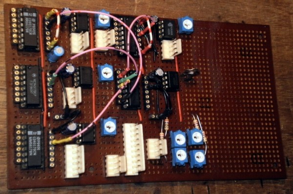
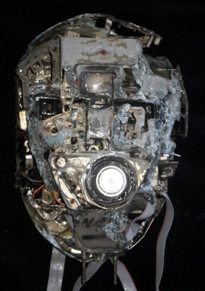
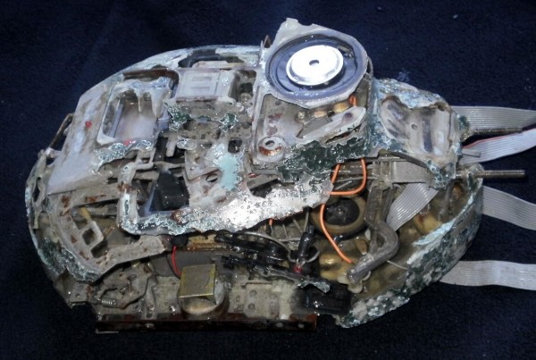
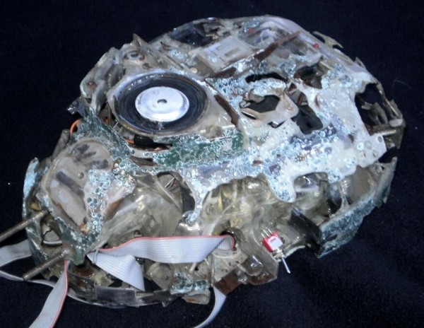
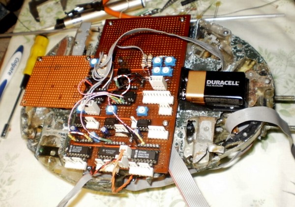
Here's a few pics of Nexus 1
| Description: |
|
| Filesize: |
113.64 KB |
| Viewed: |
457 Time(s) |
| This image has been reduced to fit the page. Click on it to enlarge. |
|
| Description: |
|
| Filesize: |
153.4 KB |
| Viewed: |
467 Time(s) |
| This image has been reduced to fit the page. Click on it to enlarge. |
|
| Description: |
|
| Filesize: |
143.44 KB |
| Viewed: |
462 Time(s) |
| This image has been reduced to fit the page. Click on it to enlarge. |
|
| Description: |
|
| Filesize: |
180.44 KB |
| Viewed: |
452 Time(s) |
| This image has been reduced to fit the page. Click on it to enlarge. |

|
_________________
What makes a space ours, is what we put there, and what we do there. |
|
|
Back to top
|
|
|
JingleJoe
Joined: Nov 10, 2011
Posts: 878
Location: Lancashire, England
Audio files: 14
|
| Posted: Fri Aug 03, 2012 5:36 am Post subject:
|
|
|
Wow that's pretty interesting, I like it  Is the face I can see in it intentional? Is the face I can see in it intentional?
_________________
As a mad scientist I am ruled by the dictum of science: "I could be wrong about this but lets find out"
Green Dungeon Alchemist Laboratories |
|
|
Back to top
|
|
|
Uncle Krunkus
Moderator
Joined: Jul 11, 2005
Posts: 4761
Location: Sydney, Australia
Audio files: 52
G2 patch files: 1
|
| Posted: Fri Aug 03, 2012 3:03 pm Post subject:
|
|
|
"Well, at this stage, we're not quite sure. Back in 2087, when it was found half caked in mud near the Swiss desert, some so called experts believed it may just be a hoax.
It is now thought to be some kind of "head". Probably an early incarnation of the Nexus droids which we now rely on so slavishly.
We've ascertained that the middle "eye" is extremely sensitive to both infra-red and ultra-violet wavelengths. The transducer on the front is currently inoperable, but we plan to replace it.
Some older parts will have to be sourced from Silicon Mountain in Malaysia, as they are too old to be replaced with anything we've used since quintelligence."
_________________
What makes a space ours, is what we put there, and what we do there. |
|
|
Back to top
|
|
|
Uncle Krunkus
Moderator
Joined: Jul 11, 2005
Posts: 4761
Location: Sydney, Australia
Audio files: 52
G2 patch files: 1
|
|
|
Back to top
|
|
|
JingleJoe
Joined: Nov 10, 2011
Posts: 878
Location: Lancashire, England
Audio files: 14
|
| Posted: Mon Aug 06, 2012 6:30 am Post subject:
|
|
|
| Uncle Krunkus wrote: | "Well, at this stage, we're not quite sure. Back in 2087, when it was found half caked in mud near the Swiss desert, some so called experts believed it may just be a hoax.
It is now thought to be some kind of "head". Probably an early incarnation of the Nexus droids which we now rely on so slavishly.
We've ascertained that the middle "eye" is extremely sensitive to both infra-red and ultra-violet wavelengths. The transducer on the front is currently inoperable, but we plan to replace it.
Some older parts will have to be sourced from Silicon Mountain in Malaysia, as they are too old to be replaced with anything we've used since quintelligence." |
Is that Philip K Dick?
The board is looking good so far good thinking for the ground connections! it;s allways good to make a distinction like that.
_________________
As a mad scientist I am ruled by the dictum of science: "I could be wrong about this but lets find out"
Green Dungeon Alchemist Laboratories |
|
|
Back to top
|
|
|
Uncle Krunkus
Moderator
Joined: Jul 11, 2005
Posts: 4761
Location: Sydney, Australia
Audio files: 52
G2 patch files: 1
|
| Posted: Mon Aug 06, 2012 2:14 pm Post subject:
|
|
|
| JingleJoe wrote: |
Is that Philip K Dick?
The board is looking good so far good thinking for the ground connections! it;s allways good to make a distinction like that. |
No, it's not, but I can't pretend he didn't inspire the idea.
Yeah, these SIL strips are very handy things to work with. The patch cords are made with the machined pins from the same SIL strips as well. They're really robust and (hopefully) reliable once they're made up. It really shifts the construction back towards the asthetic beauty which I love working with.
So far, it looks like the empty space on the board will contain 4 * 40106 complex oscillators (my term for six tolerance varied oscillators stacked on the one starved chip), and I'm thinking a chipful of AND gates may be handy. Any other suggestions? 6 chips is about all I can fit, and I still need space for an R/2R to feedback to one of the sub sequencers.
_________________
What makes a space ours, is what we put there, and what we do there. |
|
|
Back to top
|
|
|
JingleJoe
Joined: Nov 10, 2011
Posts: 878
Location: Lancashire, England
Audio files: 14
|
|
|
Back to top
|
|
|
Uncle Krunkus
Moderator
Joined: Jul 11, 2005
Posts: 4761
Location: Sydney, Australia
Audio files: 52
G2 patch files: 1
|
| Posted: Wed Aug 08, 2012 8:35 pm Post subject:
|
|
|
The 4051 definitely looks interesting Joe. I've been reading up on the data sheet. The only thing I'm not sure of is, can it be set up to act as two different types of gates, processing completely separate signals? 
I know I should be able to work that out for myself hey?
But why waste someone else's experience? 
_________________
What makes a space ours, is what we put there, and what we do there. |
|
|
Back to top
|
|
|
JingleJoe
Joined: Nov 10, 2011
Posts: 878
Location: Lancashire, England
Audio files: 14
|
| Posted: Thu Aug 09, 2012 9:02 am Post subject:
|
|
|
It processes 3 signals via the A, B and C control inputs; it acts as a 3 input gate. Different combinations of those 3 control inputs will of course connect X (the common output) to one of the eight Y inputs. (that is just what a multiplexor does)
However in this case, one is not switching between different data streams or signals using static binary combinations on the control inputs, one is putting one's signals into the control inputs and using slower LFOs or static voltages on the Y inputs to acheive the function of different gates. Heck, you can make it do things no other gate does; what with this being an analogue multiplexor you could do something like put different waveform LFOs into the Y inputs.
_________________
As a mad scientist I am ruled by the dictum of science: "I could be wrong about this but lets find out"
Green Dungeon Alchemist Laboratories |
|
|
Back to top
|
|
|
Uncle Krunkus
Moderator
Joined: Jul 11, 2005
Posts: 4761
Location: Sydney, Australia
Audio files: 52
G2 patch files: 1
|
| Posted: Fri Aug 10, 2012 3:40 pm Post subject:
|
|
|
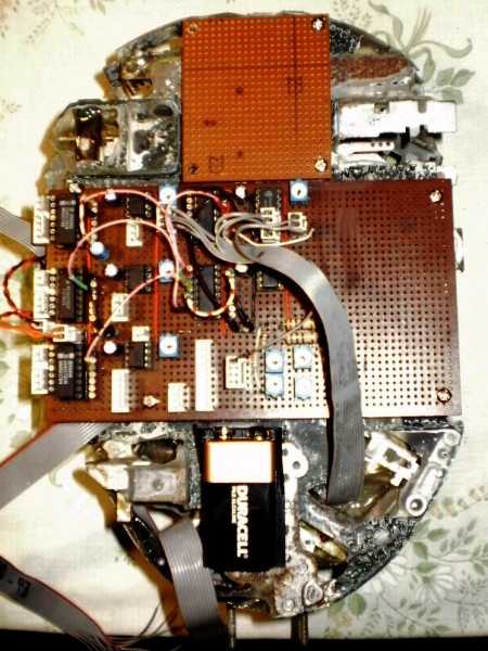
Well, I've made one definite decision.
A daughter board with Ray's WSG filter across the whole output. LDRs on the resonance and cutoff resistors, run off LEDs, with their transistors switched by XORd carry out signals from the 4017s.
_________________
What makes a space ours, is what we put there, and what we do there. |
|
|
Back to top
|
|
|
JingleJoe
Joined: Nov 10, 2011
Posts: 878
Location: Lancashire, England
Audio files: 14
|
| Posted: Sat Aug 11, 2012 2:01 am Post subject:
|
|
|
That sounds like a hell of a lot of weird sound potential (and fun )
_________________
As a mad scientist I am ruled by the dictum of science: "I could be wrong about this but lets find out"
Green Dungeon Alchemist Laboratories |
|
|
Back to top
|
|
|
Uncle Krunkus
Moderator
Joined: Jul 11, 2005
Posts: 4761
Location: Sydney, Australia
Audio files: 52
G2 patch files: 1
|
| Posted: Sat Aug 11, 2012 5:30 am Post subject:
|
|
|
| Description: |
|
| Filesize: |
210.24 KB |
| Viewed: |
446 Time(s) |
| This image has been reduced to fit the page. Click on it to enlarge. |
|
| Description: |
|
| Filesize: |
206.9 KB |
| Viewed: |
442 Time(s) |
| This image has been reduced to fit the page. Click on it to enlarge. |
|
_________________
What makes a space ours, is what we put there, and what we do there. |
|
|
Back to top
|
|
|
blue hell
Site Admin

Joined: Apr 03, 2004
Posts: 24580
Location: The Netherlands, Enschede
Audio files: 308
G2 patch files: 320
|
| Posted: Sat Aug 11, 2012 6:53 am Post subject:
|
|
|
What a crazy thing, lovely!
_________________
Jan
also .. could someone please turn down the thermostat a bit.
 |
|
|
Back to top
|
|
|
Uncle Krunkus
Moderator
Joined: Jul 11, 2005
Posts: 4761
Location: Sydney, Australia
Audio files: 52
G2 patch files: 1
|
| Posted: Mon Aug 13, 2012 1:45 am Post subject:
|
|
|
Thanks Jan, I'll take that as a compliment!
Sorry that last post was just a smiley, my keyboard wasn't working.
You can see the new daughter board for the filters, and I've mounted the battery holder and finished the power input. I have the first set of LEDs up and running. Good control of brightness, speed, and the speed interupter. More to come real soon.
_________________
What makes a space ours, is what we put there, and what we do there. |
|
|
Back to top
|
|
|
|

 Forum index » DIY Hardware and Software » Lunettas - circuits inspired by Stanley Lunetta