| Author |
Message |
Starspawn
Joined: Jun 14, 2013
Posts: 85
Location: Oslo
|
 Posted: Sun Jul 20, 2014 4:06 pm Post subject: Posted: Sun Jul 20, 2014 4:06 pm Post subject:
|
  |
|
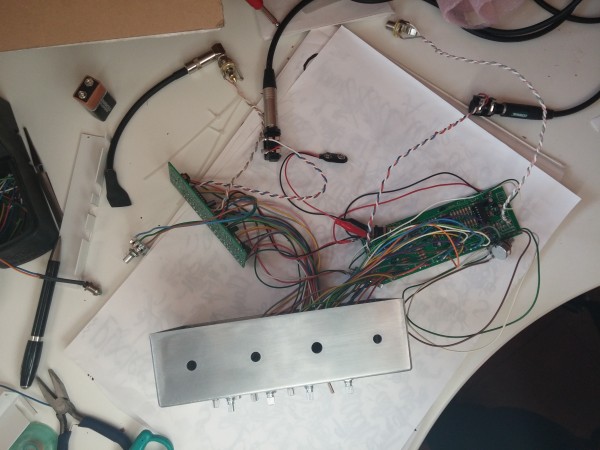
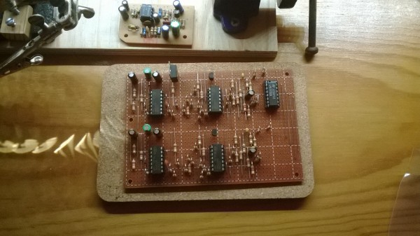
Here you go, still missing a few extras for the other pads, but sounds nice imo, good low end.
Toothbrush is is an invaluable stripboard tool, when scoring lines (after soldering to prevent tiny shorts) I put alcohol on and brush away the junk 


And sounds, just put them hard panned straight into recorder and played for a little while.
https://soundcloud.com/vintersmokk/ds7-mutand-sounds-first-try
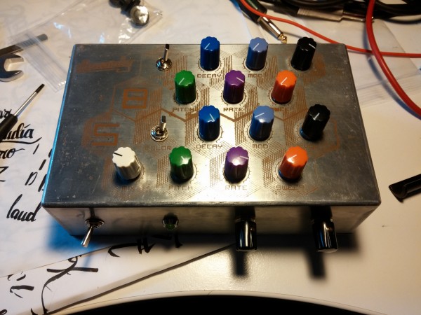
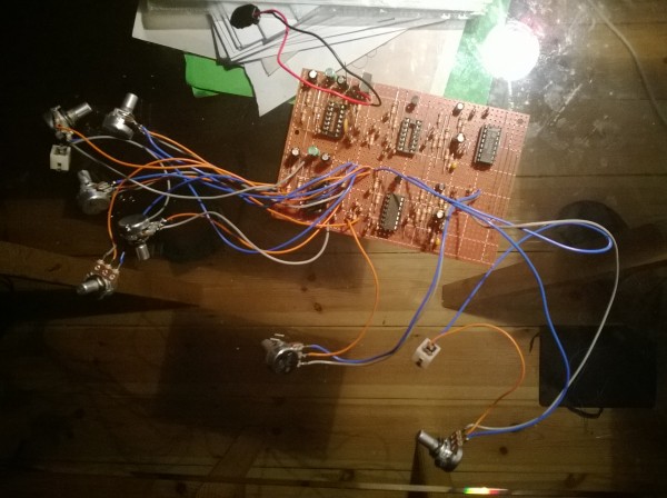
And heres the finished one btw
A synwave as left hat, synchime as right, and a monotribe Bassdrum as left pad. As well as a 6 channel panning mixer with buffer for headphone out.

Last edited by Starspawn on Sat Jan 10, 2015 7:32 am; edited 2 times in total |
|
|
Back to top
|
|
 |
tokyomatik

Joined: Jan 20, 2011
Posts: 171
Location: berlin
Audio files: 6
|
| Posted: Thu Sep 18, 2014 6:12 am Post subject:
Re: DS7 mods |
|
|
| dnny wrote: | so here are some pics of DS7 mods
first there is the VCA input mod. (for signal not for CV)
run wire from jack to leg 3 of CA3080 via 100K resistor and 100K pot.
to the panel you ad VCA input (jack) and VCA input level (pot)
and second comes the manual trigger mod:
run wire from +9V via 1M resistor to momentary push button and from there to trigger sens pot point 3.
to the panel you ad momentary push button.
(you get continuos signal if you hold the button down.)
daniel
ps. the RJWsofts Schematic Publisher is great and the pics are made whit it.
Schematic Publisher free download |
I'm trying this mod on a DS8 euro module so we are not dealing anymore with +9v but with +12v.....should I change the resistor value? Any advice? |
|
|
Back to top
|
|
|
marioguzzi
Joined: Apr 15, 2008
Posts: 18
Location: italy
|
|
|
Back to top
|
|
|
Starspawn
Joined: Jun 14, 2013
Posts: 85
Location: Oslo
|
| Posted: Sat Jan 10, 2015 6:20 am Post subject:
|
|
|
| It would probably be better to just use 1 regulator and jumper the 5V for the other circuit after that. |
|
|
Back to top
|
|
|
marioguzzi
Joined: Apr 15, 2008
Posts: 18
Location: italy
|
| Posted: Sat Jan 10, 2015 7:25 am Post subject:
|
|
|
I'm getting the exact same behaviour after bypassing the ds7's regulator.
So I tried disconnecting the ds8's output ground line: now I can hear them both, problem is this is obviously true if both of them are connected, but since only the ds7 output jack is connected to ground as soon as I disconnect it I stop getting audio from the ds8 |
|
|
Back to top
|
|
|
umschmitt

Joined: Jun 29, 2011
Posts: 189
Location: brrlin
Audio files: 11
|
| Posted: Sat Jan 10, 2015 7:52 am Post subject:
|
|
|
May sound stupid, but did you check that the signal and ground wires are not interverted at the output jack (esp. on the DS-7)?
_________________
::U::N::S::C::H::N::E::L::L:: |
|
|
Back to top
|
|
|
marioguzzi
Joined: Apr 15, 2008
Posts: 18
Location: italy
|
| Posted: Sat Jan 10, 2015 7:56 am Post subject:
|
|
|
| I thought of that but after checking I noticed that though the two pcb share the same ground I found that on the ds7 there's no continuity between ground plane and the output's ground line. I'll have to trace the pcb to check why, unluckily I have no schematics for that pcb |
|
|
Back to top
|
|
|
marioguzzi
Joined: Apr 15, 2008
Posts: 18
Location: italy
|
|
|
Back to top
|
|
|
Starspawn
Joined: Jun 14, 2013
Posts: 85
Location: Oslo
|
|
|
Back to top
|
|
|
marioguzzi
Joined: Apr 15, 2008
Posts: 18
Location: italy
|
| Posted: Sat Jan 10, 2015 9:31 am Post subject:
|
|
|
thanks for the help!
yep, I knew that schematics, my circuit is more or less the same but there are some differences from m bareille schematics like the audio output section. I got the ds7 pcb some years ago from a ebay from r shepard, but I can't find any reference to his design |
|
|
Back to top
|
|
|
Starspawn
Joined: Jun 14, 2013
Posts: 85
Location: Oslo
|
| Posted: Sat Jan 10, 2015 9:42 am Post subject:
|
|
|
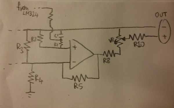
Well, lets see, R31 is your R5.
R32 is your R4.
R20, 21 and C5 is your path from the LM to + input.
All the same so far.
The difference is that your R2 and R3 is where the output from the earlier opamp should come in, but in your schematic its grounded instead!
So check if that grounding does indeed connect with the output from earlier opamp, Im sure that shouldnt be the case.
So check continuity there.
Your C1 and R4 should still be grounded. |
|
|
Back to top
|
|
|
marioguzzi
Joined: Apr 15, 2008
Posts: 18
Location: italy
|
|
|
Back to top
|
|
|
Starspawn
Joined: Jun 14, 2013
Posts: 85
Location: Oslo
|
| Posted: Sat Jan 10, 2015 10:01 am Post subject:
|
|
|
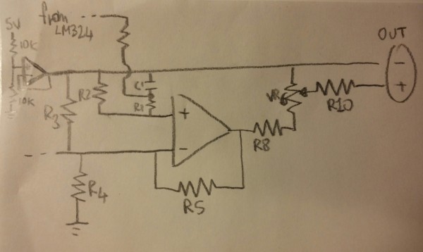
What you want to do there is cut between the R2 and C1 points, and then connect another ground point to the C1 ground/output ground.
Then it will be as the other schematic.
But be sure that youre tracing is correct first ... |
|
|
Back to top
|
|
|
umschmitt
Joined: Jun 29, 2011
Posts: 189
Location: brrlin
Audio files: 11
|
| Posted: Sat Jan 10, 2015 10:07 am Post subject:
|
|
|
So the node where R2 and R3 meet should be connected to the opamp supplying the bias voltage, not to the minus of the output (which should be your ground), as starspawn wrote. Your dotted line between R3 and R4 should lead to… nothing! Furthermore, there's no capacitor at the output of the CA3080… Maybe you zapped a couple things while reverse drawing the circuit, otherwise it's a strange design to say the least!
Edit: you posted another drawing while i was writing… Starspawn is once more right. Also please put a cap at the output of the freaking OTA!
_________________
::U::N::S::C::H::N::E::L::L:: |
|
|
Back to top
|
|
|
marioguzzi
Joined: Apr 15, 2008
Posts: 18
Location: italy
|
| Posted: Sat Jan 10, 2015 11:31 am Post subject:
|
|
|
| thanks guys, it's working fine now! |
|
|
Back to top
|
|
|
umschmitt
Joined: Jun 29, 2011
Posts: 189
Location: brrlin
Audio files: 11
|
|
|
Back to top
|
|
|
Starspawn
Joined: Jun 14, 2013
Posts: 85
Location: Oslo
|
| Posted: Sat Jan 10, 2015 11:55 am Post subject:
|
|
|
yay!  |
|
|
Back to top
|
|
|
marioguzzi
Joined: Apr 15, 2008
Posts: 18
Location: italy
|
|
|
Back to top
|
|
|
benuron
Joined: Nov 22, 2009
Posts: 11
Location: Portugal
|
|
|
Back to top
|
|
|
Starspawn
Joined: Jun 14, 2013
Posts: 85
Location: Oslo
|
| Posted: Wed Feb 18, 2015 9:47 am Post subject:
|
|
|
Looks right, but what have you done with the potentiometers when testing?
Id double check the cuts under again, and check the soldering. |
|
|
Back to top
|
|
|
benuron
Joined: Nov 22, 2009
Posts: 11
Location: Portugal
|
|
|
Back to top
|
|
|
Starspawn
Joined: Jun 14, 2013
Posts: 85
Location: Oslo
|
| Posted: Fri Mar 06, 2015 11:18 pm Post subject:
|
|
|
Yes, youve grounded the output pin in the jack sockets instead of the ring/ground pin (ground should be the lonely pin near panel), and your signal to the switched pin (so when somethings inserted its not connected).
Also not sure of the pot wiring, if you have a pot sitting on your table, with legs pointing to you, shaft up, then 1 is your leftmost pin.
Check against this: http://m.bareille.free.fr/ds7clone/ds7wiring.gif |
|
|
Back to top
|
|
|
benuron
Joined: Nov 22, 2009
Posts: 11
Location: Portugal
|
| Posted: Sat Mar 07, 2015 1:44 am Post subject:
|
|
|
Thank you Starspawn for the tips! 
This jacks have the ground ring pin on the side. I tested for continuity and the tip is not grounded.
Also double, triple checked the pots. I did the pin 1 the most left over with the shaft up (but if I wire it backwards wouldn't hurt, just the response would be on backwards  ) ) |
|
|
Back to top
|
|
|
strato54s
Joined: Mar 03, 2014
Posts: 3
Location: france
|
| Posted: Wed Mar 11, 2015 10:49 am Post subject:
helpl with mods!!!!! |
|
|
hi everyone this my first post
im rooky in electronic
i built my ds7 clone (excellent )
and i have some question
what is the difference with vca mods and cv mods?????
how to made the cv mods i dont understand the "nodal point"
This machine is excellent and so funny
(ps someone know something about this machine)
www.youtube.com/watch?v=Nv6etgvw4GE |
|
|
Back to top
|
|
|
roboter
Joined: Feb 18, 2018
Posts: 3
Location: Belgium
|
| Posted: Sun Feb 18, 2018 7:44 am Post subject:
|
|
|
| I am planning on building this, does anybody know why the filter after the VCO has such a low cutoff? Won't this cause attenuation with increasing VCO frequency? Also what is the output waveform of this VCO and is there a link where this (or a similar) VCO is explained? |
|
|
Back to top
|
|
|
|

 Forum index » DIY Hardware and Software