| Author |
Message |
PHOBoS

Joined: Jan 14, 2010
Posts: 5913
Location: Moon Base
Audio files: 709
|
|
|
Back to top
|
|
 |
DUBmatze

Joined: Feb 18, 2013
Posts: 150
Location: south Germaica (schwabilon)
|
 Posted: Wed Oct 15, 2014 2:35 pm Post subject: Posted: Wed Oct 15, 2014 2:35 pm Post subject:
|
  |
|
it is so simple with this gate / reset combi switch - i realy like it.
why are you using this Transistors at the inputs? |
|
|
Back to top
|
|
|
PHOBoS
Joined: Jan 14, 2010
Posts: 5913
Location: Moon Base
Audio files: 709
|
| Posted: Wed Oct 15, 2014 3:13 pm Post subject:
|
|
|
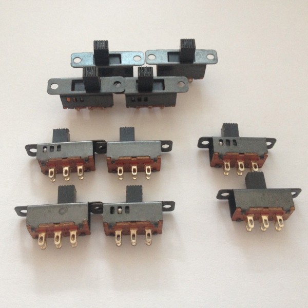
Using the switches is also much more practical than a rotary/slide switch.
The transistors give me a bit more flexibility in what I trigger it with, mostly voltage wise. Say I power it from 12V then
I could still trigger it with 5V. Another reason is that I never like to leave gates unused so I'm using those 2 NANDs
to buffer both the reset and clk inputs. But they are inverting so the transistors take care of that too.
I just noticed it says 5V in the schematic, must be a leftover from what I adjusted it from. I'm actually using 12V most of the time.
_________________
"My perf, it's full of holes!"
http://phobos.000space.com/
SoundCloud BandCamp MixCloud Stickney Synthyards Captain Collider Twitch YouTube |
|
|
Back to top
|
|
|
piedwagtail

Joined: Apr 15, 2006
Posts: 297
Location: shoreditch
Audio files: 3
|
| Posted: Wed Oct 15, 2014 4:37 pm Post subject:
|
|
|
Elegantly simple.

What does the 100pf on pin8 4093 do..is it a delay to null the 4017 latency?
And from that my concern, the short switch will allow clock PWM to pass?
Robert |
|
|
Back to top
|
|
|
PHOBoS
Joined: Jan 14, 2010
Posts: 5913
Location: Moon Base
Audio files: 709
|
|
|
Back to top
|
|
|
piedwagtail
Joined: Apr 15, 2006
Posts: 297
Location: shoreditch
Audio files: 3
|
|
|
Back to top
|
|
|
commathe

Joined: Jul 26, 2013
Posts: 153
Location: Beijing
Audio files: 5
|
| Posted: Wed Oct 15, 2014 7:54 pm Post subject:
|
|
|
| I love this, really elegant. I was trying to do something like this but was going to be using two sets of DIP switches (one for on/off and another for reset). This switching idea is much more elegant though. I just spotted some three position slide switches at one of my usual suppliers too! |
|
|
Back to top
|
|
|
PHOBoS
Joined: Jan 14, 2010
Posts: 5913
Location: Moon Base
Audio files: 709
|
| Posted: Tue Aug 25, 2015 2:24 pm Post subject:
|
|
|
I got some switches to put this one together but when looking at the schematic I noticed I made a mistake.
The way the diodes are connected would cause all the LED's that are connected to a step that is switched 'on'
to light up at the same time.  The correct way is to connect the diodes only to the switches and not the LED's. The correct way is to connect the diodes only to the switches and not the LED's.
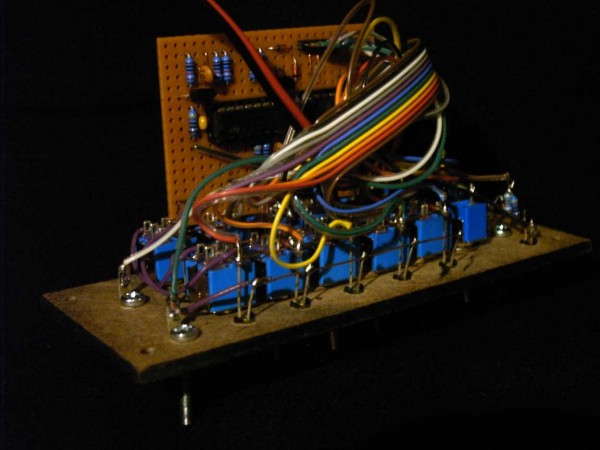
After I made that change I put the circuit together but I ran into 2 more problems. The first one was some odd
reset behaviour where it would sometimes skip the first step or bounce between a couple of steps before continuing.
This is a problem I have noticed before with the CD4017 and changing the pulldown resistor on the reset pin from
100K to 10K solved it. I also reduced the pulldown resistor on the CLKINH pin to 10K to see if that would get rid of the
the second probem, which it didn't.
This second problem was that Loop mode worked fine but x1 not all the time. Sometimes it would hold on
the selected step as it should but other times it would reset, which is kind of odd since in x1 mode the reset
pin isn't connected to any of the outputs. So it had probably something to do with the reset input. I tested of
this input was actually working and this is when I noticed some more odd behaviour. If I attached it to the
output from a divider (just something to test with) it would only run when the output was high. And when I
disconnected the wire from the divider it still wouldn't run untill I removed the patch cable completely.
So the reset input was too sensitive with the cable acting as an antenna. (it didn't work with the cable
attached when the output of the divider was low because I have diodes on the outputs so it was essentially
floating)
This made me think that it could also be causing the problem with the x1 mode not working correctly. So I
desoldered one end of the diode connected to the reset pin to have the reset input circuitry disconnected
and x1 mode worked fine now  I changed the capacitor in the reset circuit form 100pF to 1nF to see if I changed the capacitor in the reset circuit form 100pF to 1nF to see if
that would make any difference, it didn't. So next I reduced the pulldown resistor on the base of the transistor.
according to my calculations 2K4 would be about the minimum for it to work on a 5V output with a diode
and 1K resistor. I choose 4K7 to be sure and because it's a value that's already used in the circuit. And now
the circuit is working perfect.  I also replaced to pulldown resistor on the CLK for consistency, which brings I also replaced to pulldown resistor on the CLK for consistency, which brings
the number of different resistor values down to 2 (you could even use 2 10K resistors in parallel instead of 4K7
to bring it down to 1 value) The total resistance on the inputs is a bit lower than usual now.
In the schematic I also swapped the NAND gates around a bit, this is only done so it corresponds with
how I wired it up to make troubleshooting a bit easier.
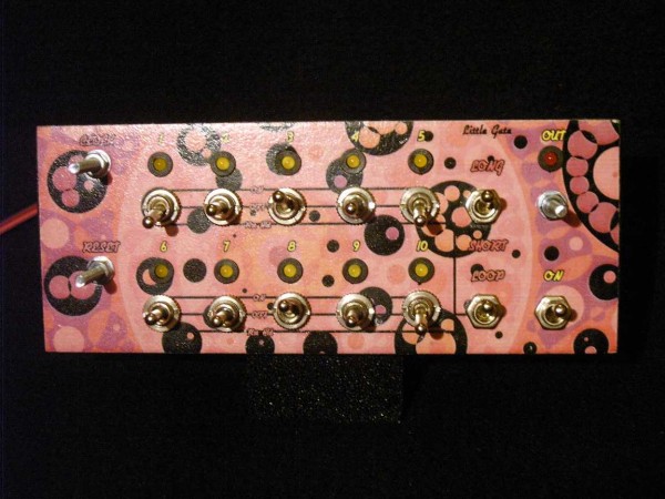
| Description: |
| Little Gate V2.0 [tested] |
|
| Filesize: |
56.94 KB |
| Viewed: |
1582 Time(s) |
| This image has been reduced to fit the page. Click on it to enlarge. |
|
| Description: |
|
| Filesize: |
89.78 KB |
| Viewed: |
861 Time(s) |
| This image has been reduced to fit the page. Click on it to enlarge. |
|
| Description: |
|
| Filesize: |
89.88 KB |
| Viewed: |
758 Time(s) |
| This image has been reduced to fit the page. Click on it to enlarge. |
|
| Description: |
|
| Filesize: |
58.99 KB |
| Viewed: |
771 Time(s) |
| This image has been reduced to fit the page. Click on it to enlarge. |
|
_________________
"My perf, it's full of holes!"
http://phobos.000space.com/
SoundCloud BandCamp MixCloud Stickney Synthyards Captain Collider Twitch YouTube |
|
|
Back to top
|
|
|
piedwagtail
Joined: Apr 15, 2006
Posts: 297
Location: shoreditch
Audio files: 3
|
| Posted: Wed Aug 26, 2015 1:50 pm Post subject:
|
|
|
Debug! Like this single resistor value idea; the 10K10step; but it's a rigor that would take space..
When I looked at this last, I was thinking about DPDT center-off switches and using the other pole to switch on programming leds and come to think of it an end of loop led(in the previous step column/position), whilst also having the run leds.
(will post NANDulator update soon!)
Robert |
|
|
Back to top
|
|
|
elektrouwe
Joined: May 27, 2012
Posts: 149
Location: Germany
|
| Posted: Thu Aug 27, 2015 4:16 am Post subject:
|
|
|
| PHOBoS wrote: | | ... Say I power it from 12V then... |
just a small hint for those who operate the circuit with 12 or even 15V:
with a single common LED resistor, the dark LEDs see a reverse voltage
>9V which some types can only stand for a short time.
At least for 15V I would spend the extra 7 Rs. |
|
|
Back to top
|
|
|
PHOBoS
Joined: Jan 14, 2010
Posts: 5913
Location: Moon Base
Audio files: 709
|
| Posted: Thu Aug 27, 2015 8:08 am Post subject:
|
|
|
I was thinking about having "on programming LEDs", didn't even realize I could have done that with the DPDT switches
I used. Use bi-color LED's. Red=steps, Green=ON which would turn yellowish when current step is ON. Hadn't thought
about adding end of loop LEDs in which case it would make more sense to use the bi-color LED's for those: Green=On
Red=reset/hold. I'm not sure if the "previous step column/position" idea would make more sense than just adding
it to the step itself. I think I do understand what you mean with it and why to do it that way but have to try it to
see what is more natural.
I was thinking of making it extendable (I actually started on something like it years ago) by adding a connector with
the 4017 outputs + CLK, so you could add more modules with switches (gate sequencer) or pots (CV sequencer).
However then it would be wise to buffer the 4017 outputs so you'd need some extra components for every module,
while it's actually more versatile to just make several complete modules that can be synced. (run them at different
speeds and step lengths)
| elektrouwe wrote: | | PHOBoS wrote: | | ... Say I power it from 12V then... |
just a small hint for those who operate the circuit with 12 or even 15V:
with a single common LED resistor, the dark LEDs see a reverse voltage
>9V which some types can only stand for a short time.
At least for 15V I would spend the extra 7 Rs. |
I see what you mean, never thought about that. Although I wonder if there is enough current to destroy the LEDs,
but better safe than sorry I guess. I used 1 common resistor because it's easier to wire up.
_________________
"My perf, it's full of holes!"
http://phobos.000space.com/
SoundCloud BandCamp MixCloud Stickney Synthyards Captain Collider Twitch YouTube |
|
|
Back to top
|
|
|
elektrouwe
Joined: May 27, 2012
Posts: 149
Location: Germany
|
| Posted: Fri Aug 28, 2015 4:54 am Post subject:
|
|
|
| PHOBoS wrote: |
I see what you mean, never thought about that. Although I wonder if there is enough current to destroy the LEDs,
|
I only had problems with modern high intensity white an blue LEDs ( which I use as low current LEDs with 1..2mA ). @ 15V (test only)supply voltage the reverse operated LEDs immediately shorted my fortunately current limited power supply. LEDs were not destroyed but damaged and showed a perament resistance in both directions and much less light output.
With old stock red and green LEDs this did not happen; they had about 10..20 uA reverse current which does not kill them.
But running Lunetta circuits with >9V isn't a good idea anyways... |
|
|
Back to top
|
|
|
Steveg

Joined: Apr 23, 2015
Posts: 184
Location: Perth, Australia
|
| Posted: Fri Aug 28, 2015 6:59 am Post subject:
|
|
|
| elektrouwe wrote: |
But running Lunetta circuits with >9V isn't a good idea anyways... |
 Why would that be the case? Why would that be the case? |
|
|
Back to top
|
|
|
piedwagtail
Joined: Apr 15, 2006
Posts: 297
Location: shoreditch
Audio files: 3
|
| Posted: Fri Aug 28, 2015 3:45 pm Post subject:
|
|
|
| Quote: | | Red=steps, Green=ON which would turn yellowish when current step is ON. |
Had me a little confuddled until I realized you mean 3 pin Bi-colour Leds not 2 pin!
| Quote: | | ...it's actually more versatile to just make several complete modules that can be synced. (run them at different speeds and step lengths) |
Yes completely agree; using step length polyrhythms is simple to set up and the results are intriguing.
R |
|
|
Back to top
|
|
|
elektrouwe
Joined: May 27, 2012
Posts: 149
Location: Germany
|
| Posted: Sun Aug 30, 2015 2:02 pm Post subject:
|
|
|
| Steveg wrote: | | elektrouwe wrote: |
But running Lunetta circuits with >9V isn't a good idea anyways... |
Why would that be the case? |
because Lunetta style means misuse of in- & outputs:
- chips run hot or even die when connecting outputs or shorting them to GND or VDD
- unbuffered gates in "analog mode": gain drops with higher VDD ( bad for twin_T bass drums and other filter and amp stuff)
- chips run hot when holding (touch-) inputs near VDD/2 or leave them open
for me the only reason to use more than 5V VDD is the drive capabilty of the outputs and Ron of 4066,405x analog switches. 6.5V is my favourite, because I still can use 74HCxx |
|
|
Back to top
|
|
|
Steveg
Joined: Apr 23, 2015
Posts: 184
Location: Perth, Australia
|
| Posted: Mon Aug 31, 2015 1:52 am Post subject:
|
|
|
| elektrouwe wrote: |
because Lunetta style means misuse of in- & outputs:
- chips run hot or even die when connecting outputs or shorting them to GND or VDD
- unbuffered gates in "analog mode": gain drops with higher VDD ( bad for twin_T bass drums and other filter and amp stuff)
- chips run hot when holding (touch-) inputs near VDD/2 or leave them open
for me the only reason to use more than 5V VDD is the drive capabilty of the outputs and Ron of 4066,405x analog switches. 6.5V is my favourite, because I still can use 74HCxx |
So if I understand you correctly what you are saying is that if I understand maximum current and power dissipation limits and don't gratuitously abuse unbuffered inverters by trying to use them as op-amps I can enjoy all the advantages the extra voltage headroom allows and still be free to power a real op-amp mixer and a small audio amp as well.
Well, why didn't you say so right off! |
|
|
Back to top
|
|
|
commathe
Joined: Jul 26, 2013
Posts: 153
Location: Beijing
Audio files: 5
|
| Posted: Mon Aug 31, 2015 6:45 am Post subject:
|
|
|
| Coming back to this: I've been mulling over using 4pdt slide switches to do this and have a reset/off/on/tie version for wonderful gate possibilities in a little package |
|
|
Back to top
|
|
|
piedwagtail
Joined: Apr 15, 2006
Posts: 297
Location: shoreditch
Audio files: 3
|
|
|
Back to top
|
|
|
commathe
Joined: Jul 26, 2013
Posts: 153
Location: Beijing
Audio files: 5
|
| Posted: Wed Sep 02, 2015 4:45 am Post subject:
|
|
|
I'm going to have to explain it verbally as I can't sketch a schematic at the moment, but it should be possible to integrate the short/long switch in the original into a 4pdt (has to be a double throw). So a step can either be on(short) or on(long) – which would act like a tied gate
Can't remember my exact working, but I remember simulating it and it being solid. It maybe needed another chip though as the short/long part has to be made separate for each step. I remember playing around with some diode logic, but I can't remember if anything came of it. |
|
|
Back to top
|
|
|
piedwagtail
Joined: Apr 15, 2006
Posts: 297
Location: shoreditch
Audio files: 3
|
| Posted: Mon Oct 19, 2015 2:33 pm Post subject:
|
|
|

in fabrication today with a second cpu board that affixes to rear!
those switches above with 2mm running leds to left 2mm step leds to right utilizing the fixing holes.
R |
|
|
Back to top
|
|
|
PHOBoS
Joined: Jan 14, 2010
Posts: 5913
Location: Moon Base
Audio files: 709
|
|
|
Back to top
|
|
|
piedwagtail
Joined: Apr 15, 2006
Posts: 297
Location: shoreditch
Audio files: 3
|
| Posted: Tue Oct 20, 2015 8:59 am Post subject:
|
|
|
No, it's 100mm.
I've shied away from eurorack because it's so 1/8" jack centric and because pcbhouses have a standard price for 100x50mm.
Actually compatible with the bolt and croc school 
R |
|
|
Back to top
|
|
|
piedwagtail
Joined: Apr 15, 2006
Posts: 297
Location: shoreditch
Audio files: 3
|
| Posted: Tue Nov 03, 2015 5:06 am Post subject:
|
|
|
I know this isn't a lingerie and beauty forum, but these are pretty!


silkscreen isn't the best I've come across - smudgy and weak in places.
Do they work? That's a known unknown at the moment, but they look good 
R |
|
|
Back to top
|
|
|
LFLab
Joined: Dec 17, 2009
Posts: 497
Location: Rosmalen, Netherlands
|
| Posted: Tue Nov 03, 2015 11:47 pm Post subject:
|
|
|
Very nice, you chose luxury by going with a coloured silkscreen!
Where did you have them made? |
|
|
Back to top
|
|
|
piedwagtail
Joined: Apr 15, 2006
Posts: 297
Location: shoreditch
Audio files: 3
|
| Posted: Wed Nov 04, 2015 1:34 am Post subject:
|
|
|
Not quite luxury....luxury would be green silkscreen on white pcb, like in the printout... . I believe some fabricators will do that.
I like the white because it makes the components look colourful and the lineage back to the slider caps on the Odyssey Mk.1 and the clean industrial design on first synth I dissected- the SEM.
These were made at Smart Prototyping, but as mentioned the black silkscreen isn't the best. Itead has been better. Cost vs speed vs customs efficiency are other factors.
R |
|
|
Back to top
|
|
|
|

 Forum index » DIY Hardware and Software » Lunettas - circuits inspired by Stanley Lunetta