| Author |
Message |
hedefalk
Joined: Aug 29, 2017
Posts: 51
Location: Stockholm, Sweden
|
 Posted: Mon May 21, 2018 1:23 pm Post subject: Posted: Mon May 21, 2018 1:23 pm Post subject:
|
  |
|
Just an update: my nudge issue turns up in KHz range, it isn't visible in lower frequencies. Also, the square and ramp is pretty slow rising/falling in the kHz range but looks ok in lower frequencies. More oscilloscope pics:
https://photos.app.goo.gl/LcX986fWeo3zwp192 |
|
|
Back to top
|
|
 |
hedefalk
Joined: Aug 29, 2017
Posts: 51
Location: Stockholm, Sweden
|
| Posted: Mon May 21, 2018 1:28 pm Post subject:
|
|
|
| Hashtag Octothorpe wrote: |
Maybe beef up your ground connections? Toss more uFs of power smoothing caps in there? Get the bypass caps closer to the power pins on the ICs?
|
Thanks! Gonna look at those suggestions. I have ground planes on both sides of the pcb, and I think I have at least 0.4mm on all power rails but I'll double check that. And I'll try to see if any of the bypass caps might be bad… |
|
|
Back to top
|
|
|
hedefalk
Joined: Aug 29, 2017
Posts: 51
Location: Stockholm, Sweden
|
| Posted: Wed May 23, 2018 3:47 am Post subject:
|
|
|
Ok, found one thing. The pulse is the one thing that looks the worst, its slow rising and falling. Noticed with the scope that that the output from 4D (pin14) peaks at 14V with a 12V supply…(!?)
So I'm thinking that's that's some kind of surge happening which might effect the other outputs through the "triangle core". Then I remembered - I was out of really high valued resistors and took a 1.5M instead of 2.2M for the feedback on the comparator for the pulse output, R53. Could this be the issue?
I guess that feedback resistor if for a bit of hysterisis? Maybe I'm better of just cutting it for now 'til I can stock up 2.2M resistors again?
* Tried that, didn't help.
* Tried beefing power rails with external wires.
* Tried beefing up with extra 104 caps on suspected IC's.
* Tried changing same IC's
* Tried beefing up electrolytcs power caps to 200 uF
Nothing of these changes helped and the oscilloscope pictures wasn't even effected so it really has to be something else that just power I think.
The pulse is starting to become a triangle already at 4kHz so it's something weird I've done here…
https://photos.app.goo.gl/amJB5CXoEDz4eyyy1 |
|
|
Back to top
|
|
|
wackelpeter
Joined: May 05, 2013
Posts: 461
Location: germany
Audio files: 10
|
| Posted: Wed May 23, 2018 9:06 am Post subject:
|
|
|
the pulse Looks like the comparator doesn't work in the expected range... the treshold seems to be too high, so that it looks like a pyramid with a flat top (which is the Point where the comparator has switched)...
If you don't have a 2M2 at hand try reducing R12 from 2K2 to 2K or 1K8 first to see if your comparator works...
As you say your Pulse is getting a triangle at 4KHz then i guess in the lower ranger it is okay or does it only look a Little bit more like a square?
Also does the Amplitude of the triangle Change when in low and then turning to higher frequencies? Does the Amplitude go down?
What kind of 555 timer you're using in the circuit?
Can you look what the triangle looks at pin8 of IC3c? I don't have much insight how the 555 and the OTA interact but to me it Looks like either the reset voltage for the timer on pin 2 or the Output of the timer (pin3) fed to the OTA to load the cap is out of range.
Maybe check all the resistor values connected to the OTA if they are as per schematic... especially i would have a look at the both 1k5 resistors... don't know if when running this on 12V those values shoudl be a bit higher like 1K8 or something... or simply the 4k7 R14 should be 4K3 or 3K9 for example... This can maybe answered by someone who has some more Knowledge and Know-how as i have..
_________________
https://soundcloud.com/bastian-j |
|
|
Back to top
|
|
|
hedefalk
Joined: Aug 29, 2017
Posts: 51
Location: Stockholm, Sweden
|
| Posted: Fri May 25, 2018 7:22 am Post subject:
|
|
|
| wackelpeter wrote: | the pulse Looks like the comparator doesn't work in the expected range... the treshold seems to be too high, so that it looks like a pyramid with a flat top (which is the Point where the comparator has switched)...
|
The threshold on 4D pin 13 I can pull from -4V to +4.4 V with the pulse witdh modulation which seems about right? I mean, I should just be able to set it at 0V and get 50% duty on the pulse.
| wackelpeter wrote: |
If you don't have a 2M2 at hand try reducing R12 from 2K2 to 2K or 1K8 first to see if your comparator works...
|
At this point I have actually disengaged the feedback resistor alltogether. That, I guess could cause some fluctuations/jitter when changing state, but that's not the problem I have here.
| wackelpeter wrote: |
As you say your Pulse is getting a triangle at 4KHz then i guess in the lower ranger it is okay or does it only look a Little bit more like a square?
|
Yes, it pretty much look ok down at the hundreds Hz at least. It seems the state change from high-low and low-high is constant time so at low frequencies it's almost perfect square but the higher I go the more obvious slow ramp I have.
| wackelpeter wrote: |
Also does the Amplitude of the triangle Change when in low and then turning to higher frequencies? Does the Amplitude go down?
|
The output triangle is 8.24Vpp constantly up to 10kHz, then it goes down to around 5.5Vpp at 20kHz
| wackelpeter wrote: |
What kind of 555 timer you're using in the circuit?
|
TS555CN, its at least CMOS…?
| wackelpeter wrote: |
Can you look what the triangle looks at pin8 of IC3c? I don't have much insight how the 555 and the OTA interact but to me it Looks like either the reset voltage for the timer on pin 2 or the Output of the timer (pin3) fed to the OTA to load the cap is out of range.
|
It's a triangle that's offset positively a lot. See picture:
https://photos.app.goo.gl/No6rQNsGLUReGTqf1
(yellow one)
| wackelpeter wrote: |
Maybe check all the resistor values connected to the OTA if they are as per schematic... especially i would have a look at the both 1k5 resistors... don't know if when running this on 12V those values shoudl be a bit higher like 1K8 or something... or simply the 4k7 R14 should be 4K3 or 3K9 for example... This can maybe answered by someone who has some more Knowledge and Know-how as i have..
|
All these are as specified.
Could bad/cheap timing caps cause these kinds of things? |
|
|
Back to top
|
|
|
wackelpeter
Joined: May 05, 2013
Posts: 461
Location: germany
Audio files: 10
|
| Posted: Fri May 25, 2018 9:52 am Post subject:
|
|
|
The Offset looks okay, have checked against one of my builds i have a 5V offset...
So your triabgle at Pin8 doesn#t have these small edges? can't see it properly in your picture...
What cap are you using for C4 (2,2nF)?
I would maybe swap the timer IC... i have used ILC7555N...
maybe post some more pics of probes from relevant Points and i can compare them to what mine look...
P.S. one short note, did you tryto power it with +/-15V i recall that you're using 12V i guess some resistor values might require some changes then to operate properly...
_________________
https://soundcloud.com/bastian-j |
|
|
Back to top
|
|
|
hedefalk
Joined: Aug 29, 2017
Posts: 51
Location: Stockholm, Sweden
|
| Posted: Mon May 28, 2018 3:17 am Post subject:
|
|
|
| wackelpeter wrote: | The Offset looks okay, have checked against one of my builds i have a 5V offset...
So your triabgle at Pin8 doesn#t have these small edges? can't see it properly in your picture...
|
Yes, exactly - these edges/nudges are on pin 14 but not pin 8.
| wackelpeter wrote: |
What cap are you using for C4 (2,2nF)?
|
It's pretty cheap green poly film caps, this kind https://www.aliexpress.com/item/New-50pcs-Polyester-film-capacitor-100V-0-33NF-0-82NF-5-6NF-10NF-2-7NF-3/32831235621.html?spm=a2g0s.9042311.cb0001.3.27424c4d9jlXT7&scm=1007.13441.76633.0&pvid=89bc5a10-0b5e-4f06-b535-58300f923d8e&tpp=1
I tried using another similarly sized cap in parallell if that would change the size of the nudge, but it looked the same, just half frequency. But since the nudge isn't present on pin 8 but just after the triangle buffer I figured it's not worth the work of desoldering that one. But on the other hand, the nudge is also somewhat present on the ramp which isn't using the "triangle core" connection (pin 15 on IC3D I mean).
| wackelpeter wrote: |
I would maybe swap the timer IC... i have used ILC7555N...
|
Had some 7555 smds that I tried with using a dip converter pcb now. No change at all.
| wackelpeter wrote: |
maybe post some more pics of probes from relevant Points and i can compare them to what mine look...
|
Thanks, that's very helpful! I'll get back!
| wackelpeter wrote: |
P.S. one short note, did you tryto power it with +/-15V i recall that you're using 12V i guess some resistor values might require some changes then to operate properly...
|
The only thing I did was fonik's suggestion of changing R27 to 3K and raised the R24 trimmer to 50K I think. It was a while ago I read the whole thread, did anything else turn up as a change suggestion to the original schematic? |
|
|
Back to top
|
|
|
wackelpeter
Joined: May 05, 2013
Posts: 461
Location: germany
Audio files: 10
|
| Posted: Mon May 28, 2018 10:37 am Post subject:
|
|
|
Have you made any progress yet?
I looked again through the schematics i printed out before stripboarding the whole and i noticed that i changed some resistor values too as i have handwritten other values somewhere... R33 original a 100K Looks like i have changed to a 120K... i don't know why, perhaps i had some Problems getting a proper and straight ramp...
What came to my mind as your comparator/pulse Output behaves somehow strange have you disconnected it and checked the other waveforms again? As your initial triangle seems to be ok, i think narrowing it down by disconnecting possible sources of misbehaviour could bring us a step or two further, or eventually not... Maybe desolder one lug of R12 and check again, then perhaps cut the trace between pin 8 of IC3c and IC3d pin12...
If the failure was somewhere there then you should have at least a proper ramp after calibrating the ramp-waveform.
or other ideas would be to disconnect also R26 and R34 where they connect to pin 14 of IC3d. BTW. R34 i have marked as 56K (can't remember now if this change was related to the Output voltage or waveform...)
P.S. one further note.. have you already swapped the LM13700? had this 2 or 3 times that only one half of the IC was working and the other broken...
_________________
https://soundcloud.com/bastian-j |
|
|
Back to top
|
|
|
hedefalk
Joined: Aug 29, 2017
Posts: 51
Location: Stockholm, Sweden
|
| Posted: Wed May 30, 2018 6:37 am Post subject:
|
|
|
| wackelpeter wrote: | Have you made any progress yet?
|
Not really  It's lying on the desk in front of me staring, trying to pock my attention… It's lying on the desk in front of me staring, trying to pock my attention…
| wackelpeter wrote: |
I looked again through the schematics i printed out before stripboarding the whole and i noticed that i changed some resistor values too as i have handwritten other values somewhere... R33 original a 100K Looks like i have changed to a 120K... i don't know why, perhaps i had some Problems getting a proper and straight ramp...
|
That's interesting…
| wackelpeter wrote: |
What came to my mind as your comparator/pulse Output behaves somehow strange have you disconnected it and checked the other waveforms again? As your initial triangle seems to be ok, i think narrowing it down by disconnecting possible sources of misbehaviour could bring us a step or two further, or eventually not... Maybe desolder one lug of R12 and check again, then perhaps cut the trace between pin 8 of IC3c and IC3d pin12...
If the failure was somewhere there then you should have at least a proper ramp after calibrating the ramp-waveform.
|
I disconnected R12 and I still have the nudge on the triangle so that definitely means the pulse comparator isn't to blame.
| wackelpeter wrote: |
or other ideas would be to disconnect also R26 and R34 where they connect to pin 14 of IC3d. BTW. R34 i have marked as 56K (can't remember now if this change was related to the Output voltage or waveform...)
|
I guess changing R34 would be to increase the gain of the sine since it's a bit low as is. Mine's 4.8Vpp while the triangle is 9.6Vpp.
| wackelpeter wrote: |
P.S. one further note.. have you already swapped the LM13700? had this 2 or 3 times that only one half of the IC was working and the other broken...
|
I know I've replaced at least once, but I think that was since I burnt it  I'll try that… I'll try that…
No change replacing the ota.
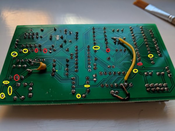
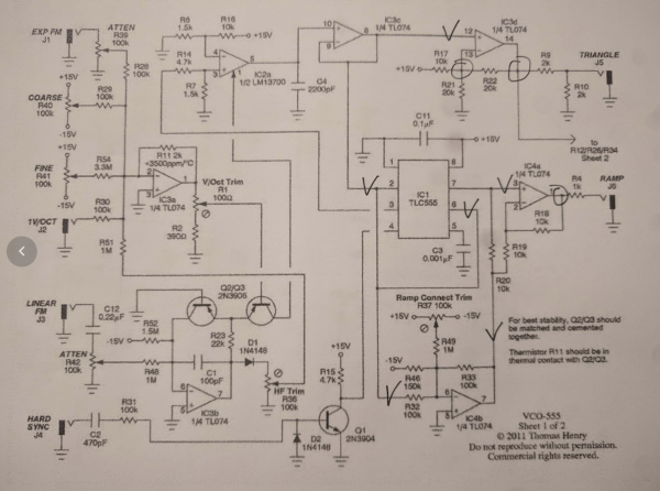
Ok, so now I have systematically just marked on the schematic where I have the nudges and where I don't, and turns out I have it on what I would consider different places not connected by anything but signals that _doesn't_ have it. I've marked with rings where the nudge is present and where with ticks where it isn't. As you can see, it's present on both the triangle and ramp outputs but not any shared connection between the two. Other than power rails that is…
https://photos.app.goo.gl/RYWvpgKMGVF9e4rX6
I feel this really has to mean there's some kind of power surge thing. I've replaced IC3 and IC4 many times so not them.
Also before disconnecting the pulse out, I measured it again and it really did peak at something like +14V. That gotta mean it's draining from a cap somewhere or what does it mean?
How does this work - a comparator that just goes max high or low, I've just thought that would be something a little less than the power rails, but in my case it actually peaks at more… Anyway, that's a sidetrack 'cos the pulse output isn't even connected now and I still have that dint.
One more picture - this is 555 pin 7 yellow vs ramp out blue:
https://photos.app.goo.gl/LaFcipulM7stV4bE3
One thing, I'm not using 10uF power caps, but 22uF, that's gotta be ok right? |
|
|
Back to top
|
|
|
wackelpeter
Joined: May 05, 2013
Posts: 461
Location: germany
Audio files: 10
|
| Posted: Wed May 30, 2018 9:43 am Post subject:
|
|
|
hmm... could be some PSU related... but i guess you're running the VCO alone on this PSU for testing purposes and Trouble Shooting... if not then disconnect everything else and see how it behaves then...
The 22uF are no prob... you can go also higher, with only keeping an eye on the max. capacitance load of your PSU as all these caps will be loaded when powered up...
Do you have installed all the decoupling caps (100nF) on the power rails for each IC? I highly recommend to use them and put them on board if you haven't done that already...
Also maybe tell us the exact part number of your TL074... perhaps this is some exotic brand or with some exotic specifics... also swapping it for anotherTL0x4 OpAmp or any pin compatible replacement could rule this one out...
Have you scoped and put a DVM on your power rails... is it stable or are there little drifts in Voltage (a few mV would be also audible recognizable in small pitch shifts)
Also i would have a look at the solder Points again, especially the power Inputs for the IC's or around the comparator section and the whole timer IC, as a Connection can Show good results when the VCO is unpowered but with some load and current running through this connections Things can look different (well okay it's not in the region of value of the currents in normal electricity where this can occur, but that's one of the very few ideas i still have)
You see me a bit helpless here, i guess at least now it's time for some proper professional help from a few more experienced people here...
_________________
https://soundcloud.com/bastian-j |
|
|
Back to top
|
|
|
hedefalk
Joined: Aug 29, 2017
Posts: 51
Location: Stockholm, Sweden
|
| Posted: Wed May 30, 2018 11:06 am Post subject:
|
|
|
| wackelpeter wrote: | | hmm... could be some PSU related... but i guess you're running the VCO alone on this PSU for testing purposes and Trouble Shooting... if not then disconnect everything else and see how it behaves then... |
I've been running it from both my Doepfer case as well as my labb psu which is something similar to the MFOS wall wart one I made myself. Same result on both.
| wackelpeter wrote: |
Do you have installed all the decoupling caps (100nF) on the power rails for each IC? I highly recommend to use them and put them on board if you haven't done that already...
|
Yes. I also did add extra ones by holding in place just to check. Not very systematically though, I might want to revisit that idea.
| wackelpeter wrote: |
Also maybe tell us the exact part number of your TL074... perhaps this is some exotic brand or with some exotic specifics... also swapping it for anotherTL0x4 OpAmp or any pin compatible replacement could rule this one out...
|
Need to check that but good idea to switch to something else alltogether. I think it is these I'm using, TI TL074CN: https://www.aliexpress.com/snapshot/0.html?spm=a2g0s.9042647.6.1.34944c4dq8Wr4H&orderId=84912726447440&productId=32703907165
| wackelpeter wrote: |
Have you scoped and put a DVM on your power rails... is it stable or are there little drifts in Voltage (a few mV would be also audible recognizable in small pitch shifts)
|
Actually I haven't, that's definitely a good idea
| wackelpeter wrote: |
Also i would have a look at the solder Points again, especially the power Inputs for the IC's or around the comparator section and the whole timer IC, as a Connection can Show good results when the VCO is unpowered but with some load and current running through this connections Things can look different (well okay it's not in the region of value of the currents in normal electricity where this can occur, but that's one of the very few ideas i still have)
|
I'll do that! Some kind of power issue for IC4 feels like the most reasonable explanation to me.
| wackelpeter wrote: |
You see me a bit helpless here, i guess at least now it's time for some proper professional help from a few more experienced people here... |
Thank you so much so much for your help so far! Every time I get an answer here I get new energy to try out things. |
|
|
Back to top
|
|
|
hedefalk
Joined: Aug 29, 2017
Posts: 51
Location: Stockholm, Sweden
|
| Posted: Thu May 31, 2018 12:05 am Post subject:
|
|
|
Tried swapping IC4 to an LM324N with the same results.
Resoldered all pins on IC4's socket.
Checked the power pins for any visible fluctuations on IC4 but nothing visible on the scope. It does however say something like MIN 12V, MAX 13.8V or so, but the visible line is pretty damn straight with just little little noise. Nothing close to resembling the nudge on the output signals. I think that measured span is the same just measuring the power connection straight from my PSU without anything even connected.
If it was underdimensioned bypass caps (they're all 104's close to the ic's) that would really been shown as a voltage loss at the power pins in the same range as the nudge on the output, wouldn't it?
What I think is a key realisation for me is that both the ramp and triangle outputs have this issue, while the things going INTO them doesn't. The only thing they share is just physical location being on the same package… But switching IC's hasn't helped so… Yeah, I'm really out of ideas.
Hm, trying out the caps… Just realized also that I've been using 104's as bypass caps but the schematic actually calls for 103's? It says "6 * 0.01uF". That's 10nF = 103, right? I'm just so used to sticking 100nF everywhere… |
|
|
Back to top
|
|
|
elmegil

Joined: Mar 20, 2012
Posts: 2179
Location: Chicago
Audio files: 16
|
| Posted: Thu May 31, 2018 12:20 am Post subject:
|
|
|
| hedefalk wrote: | | Hm, trying out the caps… Just realized also that I've been using 104's as bypass caps but the schematic actually calls for 103's? It says "6 * 0.01uF". That's 10nF = 103, right? I'm just so used to sticking 100nF everywhere… |
That really shouldn't matter. 104's are more common as bypass, 103's are valid too. |
|
|
Back to top
|
|
|
tömbszelence
Joined: Aug 12, 2012
Posts: 6
Location: Hungary
|
| Posted: Thu May 31, 2018 3:32 am Post subject:
|
|
|
Is this how the sync should sounds on this oscillator? I don't really know how it should sound but i have heard more harmonic content on pretty much everyone else's videos.
I explain everything in the video. In the last few seconds i add some distortion so you can hear what this should sounds like with a lot of high harmonics.
http://www.youtube.com/watch?v=upSEeU7bzxk
(i put a constant voltage into the Exp FM inputs and detune the oscillators from there so i don't have to retune the main tuning pots everytime i do this, i just remove the cables from the FM inputs to return to the original tuning.) |
|
|
Back to top
|
|
|
Hashtag Octothorpe
Joined: Jun 11, 2017
Posts: 57
Location: Grand Rapids MI
|
| Posted: Thu May 31, 2018 5:23 pm Post subject:
|
|
|
| hedefalk wrote: |
What I think is a key realisation for me is that both the ramp and triangle outputs have this issue, while the things going INTO them doesn't. The only thing they share is just physical location being on the same package… But switching IC's hasn't helped so… Yeah, I'm really out of ideas.
|
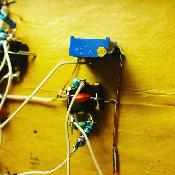
I finally got two of these oscillators working. Turns out for me, the 7555 chips didn't work, it *needed* to be actual TLC555s.
Funny story, I was putting away my stuff and noticed that three TLC555s were missing out of the tube, and was like "Huh? Where did it go?!?!?" and when I got the circuit built the PWM section wasn't working -- the triangle wave was coming through!?!??? Through a comparator???
I fiddled and looked, and the TL072 I was using for the pulse waveshaper said TL(obscured by flux)55 and I was like WHAT so that's where that pesky chip went!
Aaaanyway, with the timer chip replaced by a op amp (threw the timer away, probably 24V across pins 8 and 4 blew it???) the PWM circuitry works great. And I'm noticing the exact little "nudge" that hedefalk has noticed, but farther down on the scope. Mine is there at lower frequencies as well as higher, but I don't notice it on the sine, just the ramp and tri. I can't hear it so it doesn't really bother me.
| Description: |
| The offending TLC555, masquerading as an op amp. The scamp. |
|
| Filesize: |
86.34 KB |
| Viewed: |
442 Time(s) |
| This image has been reduced to fit the page. Click on it to enlarge. |
|
|
|
|
Back to top
|
|
|
hedefalk
Joined: Aug 29, 2017
Posts: 51
Location: Stockholm, Sweden
|
| Posted: Thu May 31, 2018 10:30 pm Post subject:
|
|
|
| Hashtag Octothorpe wrote: |
I finally got two of these oscillators working. Turns out for me, the 7555 chips didn't work, it *needed* to be actual TLC555s.
|
Huh, I actually tried with replacing the TS555CN I was using with an SMD 7555. It seemed to work fine for me. At least for a while, but then after probing a lot it died on me. I thought I had shorted something so just went back to the TS555CN.
On the nudge issue: well, actually I have been feeling maybe I'm a little bit of a princess on a pea there. It's a pretty small nudge that gets visible from maybe around 2kHz and more and more visible the further up I go. But I actually haven't even listened to the VCO yet, just used a scope
However, the second problem is that ramp and pulse are pretty slow rising at these frequencies too. I mean, here's the pulse again at 4.4kHz:
https://photos.app.goo.gl/TeQ6c6xnCEVhP1CH2
Rise/fall time seems pretty constant so at 9kHz the pulse does become a triangle.
Ramp isn't as bad, but still this can't be right can it?
https://photos.app.goo.gl/CjwWi30waHFfuVvj1 |
|
|
Back to top
|
|
|
hedefalk
Joined: Aug 29, 2017
Posts: 51
Location: Stockholm, Sweden
|
| Posted: Fri Jun 01, 2018 4:14 am Post subject:
|
|
|
| hedefalk wrote: |
Ramp isn't as bad, but still this can't be right can it?
|
No, definitely not. Slew rate of TL07X should be 10V/uS and this is something like factor 50 from that at least. The square slew is waay more than that: https://photos.google.com/photo/AF1QipMQBFeboNE66KXS4dfbymDXrqAg6pgpew-5e0d0
There must be some short to some cap somewhere right? Or something something. This is killing me! |
|
|
Back to top
|
|
|
wackelpeter
Joined: May 05, 2013
Posts: 461
Location: germany
Audio files: 10
|
| Posted: Fri Jun 01, 2018 7:49 am Post subject:
|
|
|
Perhaps also post some pics of your VCO from both sides of the PCB, maybe someone can spot something we didn't discovered yet.
_________________
https://soundcloud.com/bastian-j |
|
|
Back to top
|
|
|
hedefalk
Joined: Aug 29, 2017
Posts: 51
Location: Stockholm, Sweden
|
| Posted: Thu Jun 07, 2018 7:17 am Post subject:
|
|
|
| wackelpeter wrote: | | Perhaps also post some pics of your VCO from both sides of the PCB, maybe someone can spot something we didn't discovered yet. |
Hehe, I was a bit reluctant since this really isn't my proudest piece of output, but here it goes:
https://photos.app.goo.gl/yFzUq0QtT2W3MguD2
I think this was the first PCB I made as part of learning KiCad. I also wanted to home etch it at first so really tried hard to minimize no of vias, but somewhere in the middle said fuck it and when with jlcpcb. So there are very weird placement/routing choices I guess.
Also made the following errors already at schematic:
* mirrored one of the expo transistors
* mirrored an opamp in the pulse output
* made one too few bypass caps which I for some reason didn't even notice on the layout later
These errors are patched though:
* Resoldered Q 180 degrees
* cut a trace and added wires for the opamp
* added bypass cap on back side
Aaand also soldering is pretty bad, I think I had a really worn out tip and I never cleaned out the flux, but I haven't found any bad connection or short and I did reflow a few suspicious places. I don't think mentioned schematic errors are to blame, I think all the fixes are solid. The cables and bypass caps are _not_ shorting anything, promise |
|
|
Back to top
|
|
|
wackelpeter
Joined: May 05, 2013
Posts: 461
Location: germany
Audio files: 10
|
| Posted: Thu Jun 07, 2018 9:56 am Post subject:
|
|
|
there are some suspicious Looking solder Points... if i'm not totally wrong from the first glance i would say there could be the culprit among them…
Also i would clean the flux, flux can cause several problems, especially when it's between the traces and can cause capacitances or other things...
Also what Solder do you use, is this lead free??? I only use SN60PB39CU1 solder wire, that flows best, unless it's not healthy if you inhale this too much… (reason to Keep a nice airflow over your workplace or wear a small mask over nose and mouth (which for doesn'T work out for me as it's really uncomfortable))…
Would be my first tip to get some better solder wire and perhaps check the temperature youu're soldering with… not too hot and not too Cold...
_________________
https://soundcloud.com/bastian-j |
|
|
Back to top
|
|
|
hedefalk
Joined: Aug 29, 2017
Posts: 51
Location: Stockholm, Sweden
|
| Posted: Thu Jun 07, 2018 10:05 am Post subject:
|
|
|
I felt so ashamed right after posting those images that I re-wet all solder points and brushed it all with isopropanol.
https://photos.app.goo.gl/HKVW4Sg1xQeQ9KQH3
Still no change though |
|
|
Back to top
|
|
|
wackelpeter
Joined: May 05, 2013
Posts: 461
Location: germany
Audio files: 10
|
|
|
Back to top
|
|
|
hedefalk
Joined: Aug 29, 2017
Posts: 51
Location: Stockholm, Sweden
|
| Posted: Thu Jun 07, 2018 1:20 pm Post subject:
|
|
|
| wackelpeter wrote: |
some of the point's i've noticed i have marked red and yellow… |
Thanks! I'll double check all these tomorrow! |
|
|
Back to top
|
|
|
hedefalk
Joined: Aug 29, 2017
Posts: 51
Location: Stockholm, Sweden
|
| Posted: Sat Jun 09, 2018 2:48 pm Post subject:
|
|
|
Have I've possibly been chasing just normal crossover distortion? https://youtu.be/VgodYtiD_F0
Could someone confirm they have better looking waves at 4kHz+? |
|
|
Back to top
|
|
|
hedefalk
Joined: Aug 29, 2017
Posts: 51
Location: Stockholm, Sweden
|
|
|
Back to top
|
|
|
|

 Forum index » DIY Hardware and Software » Thomas Henry designs