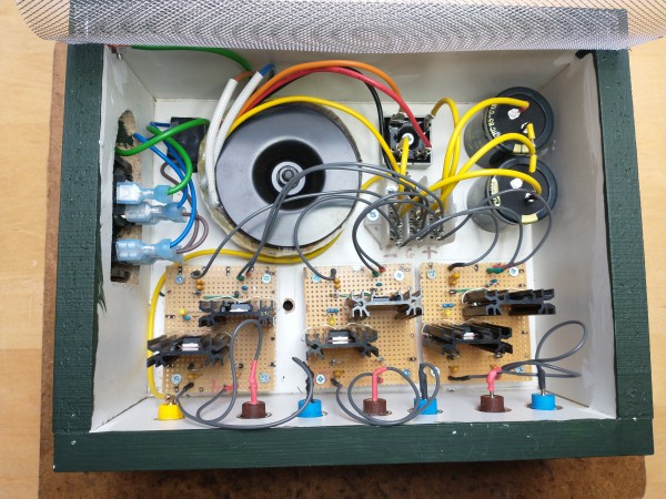
Finally built a transformer-based power supply, until now I've used Ray Wilson's wall-wart based system. Enough current capacity for three of my cabinets.
IMG_20220303_122910960.jpg
Description:
Filesize:
5.28 MB
Viewed:
360 Time(s)
This image has been reduced to fit the page. Click on it to enlarge.
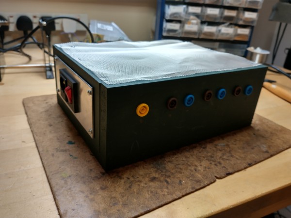
IMG_20220303_123020541_HDR.jpg
Description:
Filesize:
3.16 MB
Viewed:
323 Time(s)
This image has been reduced to fit the page. Click on it to enlarge.
Should be able to supply 1A on both +12V and -12V from each of the three regulator boards. Yes, the mesh is for airflow, and is of course safety earthed (before anyone asks).
and is of course safety earthed (before anyone asks).
Heh, that one is visable in the top image.
Nice box - at first wondered what the yellow output was for, but then realized that there is just one ground connector - probably. _________________ Jan
also .. could someone please turn down the thermostat a bit.
9 3 4 .. erm .. not 13 then? .. hmm, ah eight! .. yeah yeah as in 8647 .. 47 is an 88 .. pwew .. numbles!
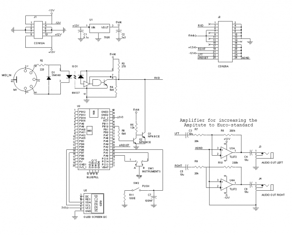
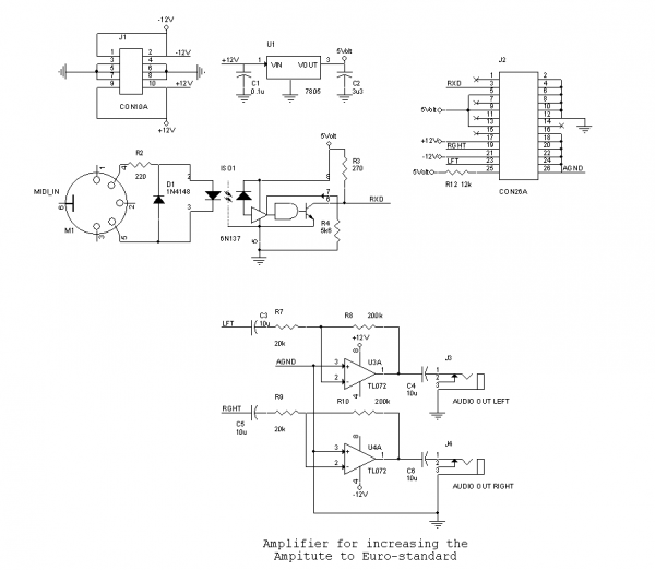
Thanks, but no, the opamp before the LED is a comparator and the purpose of the offset opamp is twofold: it is there to enable the use of the zener diodes.
By applying a buffer connected to the wiper of the offset pot, the impedance as seen by the zener diodes is 100k / 4 = 25k independent from the positions of the wipers. If I didn’t use buffers there, turning one wiper would influence all other offsets.
Secondly, by using a buffer the impedance as seen from the -input of U1B does not change by moving the wiper of the offset pot, so the amplification by U1B is constant and unaffected by the position of the offset wiper. _________________ my synth
Joined: Jan 14, 2010 Posts: 5969 Location: Moon Base
Audio files: 709
Posted: Thu May 05, 2022 12:09 pm Post subject:
hmm I still have one of those blue pills,. or maybe 2.
but ehm,. no CV inputs ?
delays are fun when you can modulate them and I assume that the pots for adjusting the parameters just create a DC voltage,
so I guess that shouldn't be to hard to add.
I haven’t been able to make a smooth transition from one setting of the LENGTH potentiometer (the only potmeter measured by the blue pill) to the other, so creating a cv input was not feasible.
Perhaps if I have time to spair in the future I will have a next look and maybe a next iteration of this module.
The blue pill is used for its speed, but the ram was insufficient for practical delay times so I added external memory for a total of 2MBit.
In addition I used a 16 bit ADC and a 16 bit DAC.
Alas, the ADC of the blue pill is only 12 bits, so each smallest step of the LENGTH potmeter will lengthen or shorten the delay by 32 samples
(32 samples x 16 bits x 4095 = 2MBit)
if your AD sampling is fast enough (or the time modulations slow enough) .. you could add analog(ish) noise and smooth the signal in the digital domain .. maybe ...
(ish) because analog noise is a bit messy to make it consistant .. so something with a pseudo random generator I guess.
This would not allow for abrupt changes, they will give some artifacts .. but could still be worthwile?
Edit: btw: was wondering .. did not hear any artifacts on changing the delay time in you vid? are you resizing and re-initializing the buffer maybe? or it may be my ears ;)
Edit2: or when the processor makes the noise .. it could be a saw siganl too .. to be added to the input signal .. to see where the transition is .. to get the extra bits.
Anyway - just some late night ideas :' ) _________________ Jan
also .. could someone please turn down the thermostat a bit.
9 3 4 .. erm .. not 13 then? .. hmm, ah eight! .. yeah yeah as in 8647 .. 47 is an 88 .. pwew .. numbles!
Hope you didn’t lost any sleep over this module Jan 😔
Valuable tips to keep in mind! The reason you didn’t hear transitions maybe because I sample the potmeter once every 1024 samples? _________________ my synth
1024 .. being still, say, about 44Hz @ 44kHz - must be my ears _________________ Jan
also .. could someone please turn down the thermostat a bit.
9 3 4 .. erm .. not 13 then? .. hmm, ah eight! .. yeah yeah as in 8647 .. 47 is an 88 .. pwew .. numbles!
Joined: Jan 14, 2010 Posts: 5969 Location: Moon Base
Audio files: 709
Posted: Mon Jun 06, 2022 5:21 am Post subject:
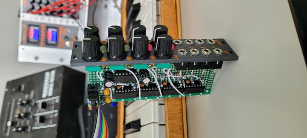
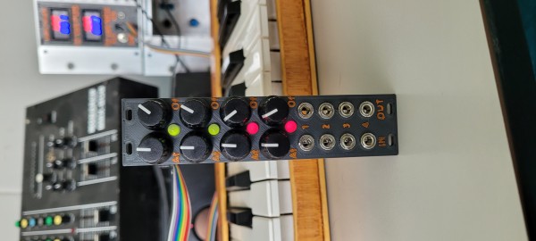
I finally finished something (after waiting about 5 months to get some pots) ; a modified SIMA Edit 2 video enhancer.
You can see some of it in this video though my capture device + compression doesn't leave much of it intact.
It was also used for this video but that one also relies heavily on the Edirol V-4.
I also finished some video modules but I don't have any powercables and since I can't use them it doesn't feel like they are finished.
I might take some photos anyway but then I want to add more info + schematics aswell.
Joined: Mar 11, 2014 Posts: 746 Location: New Zealand
Audio files: 41
Posted: Mon Jun 27, 2022 7:57 pm Post subject:
Super chuffed that I got this sorted! Runs fairly well on 12V, didn't end up needing a DC-DC converter at all.
Did all the dome filter passive components with SMD, as I figured it was easier to source high accuracy components in that package (and, certainly, it would fit in Eurorack better!)
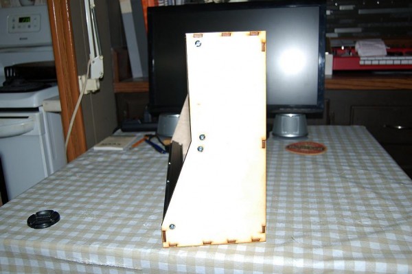
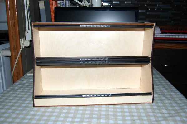
I was cutting out some puzzles on my 50 watt laser cutter, and thought I should try cutting out a case.
The laser has a cutting bed of 510mm x 300mm, so I drew up a 84hp, 6u case in Sketchup, and cut it out, the sides are 6mm baltic birch plywood, and the top, bottom,back, front are 3mm.
I think it turned out pretty good.
Now I have to do one out of acrylic.
DSC_1818.JPG
Description:
Filesize:
42.99 KB
Viewed:
206 Time(s)
This image has been reduced to fit the page. Click on it to enlarge.
DSC_1816.JPG
Description:
Filesize:
61.23 KB
Viewed:
194 Time(s)
This image has been reduced to fit the page. Click on it to enlarge.
DSC_1815.JPG
Description:
Filesize:
70.44 KB
Viewed:
236 Time(s)
This image has been reduced to fit the page. Click on it to enlarge.
You cannot post new topics in this forum You cannot reply to topics in this forum You cannot edit your posts in this forum You cannot delete your posts in this forum You cannot vote in polls in this forum You cannot attach files in this forum You can download files in this forum

 Forum index » DIY Hardware and Software


![SIMA edit2 - 1 [20220530].jpg](phpbb-files/thumbs/t_sima_edit2__1_20220530_966.jpg)