| Author |
Message |
nativeVS
Joined: Dec 12, 2017
Posts: 14
Location: London
|
 Posted: Sun Jun 14, 2020 10:48 am Post subject: Posted: Sun Jun 14, 2020 10:48 am Post subject:
|
  |
|
| ryktnk wrote: | | When you were using calibration test mode, did the Pots and Stage Count switches test ok. |
Pots and Count switches are all testing fine.
| ryktnk wrote: | Can you turn on the sequencer.
Stop the clock.
Select a stage with the NXT PRV buttons, and measure the voltage on the pin from the previous post, whilst adjusting the Gate Mode switch.
PS this is voltage that is sent to the processor for Gate Modes. |
3.3V in the bottom position, 0.22V in any other.
Thanks for the help, Robert. |
|
|
Back to top
|
|
 |
ryktnk

Joined: Apr 24, 2008
Posts: 285
Location: london
Audio files: 1
|
| Posted: Mon Jun 15, 2020 8:13 am Post subject:
|
|
|
| nativeVS wrote: | | ryktnk wrote: | | When you were using calibration test mode, did the Pots and Stage Count switches test ok. |
Pots and Count switches are all testing fine.
| ryktnk wrote: | Can you turn on the sequencer.
Stop the clock.
Select a stage with the NXT PRV buttons, and measure the voltage on the pin from the previous post, whilst adjusting the Gate Mode switch.
PS this is voltage that is sent to the processor for Gate Modes. |
3.3V in the bottom position, 0.22V in any other.
Thanks for the help, Robert. |
Hello
For the Stage Gate Mode voltage you should be seeing about out 4.3v
on the long gate setting, and 0.8v on the single gate setting, and 0v on the
no-gate setting, and aprrox 0.8v steps between each setting.
Please check carefully R19, make sure there is continuity to GND on the LHS leg.
Also check the following resistors carefully:
R20,R22,R26,R28,R30,R32.
These form the voltage dividers for the different switch settings.
ryk |
|
|
Back to top
|
|
|
nativeVS
Joined: Dec 12, 2017
Posts: 14
Location: London
|
| Posted: Mon Jun 15, 2020 10:35 am Post subject:
|
|
|
All resistor for the potential divider are correct; R19 measures around 210k without the main pcb, and 127R with it connected.
Other 'fun' things are best illustrated in the following table which shows the voltage across the various resistors of the divider depending on the switch position (all measured in test mode).
| Code: |
R19 R20 R22 R26 R28 R30 R32
1 0.104 0.101 0.096 0.090 0.083 0.071 0.053
2 0.104 0.256 0.460 0.731 1.104 1.915 4.6
3 0.105 0.412 0.826 1.393 2.22 4.58 3.12
4 0.106 0.685 1.479 2.61 4.56 3.74 2.70
5 0.107 1.075 2.42 4.53 4.12 3.44 2.53
6 0.110 1.892 4.51 4.22 3.86 3.25 2.42
7 0.119 4.47 4.26 4.01 3.68 3.11 2.34
8 3.31 3.20 3.06 2.88 2.65 2.25 1.70 |
Whilst I can easily understand the open position, all others seem to suggest some current issues; sad.
Robert |
|
|
Back to top
|
|
|
ryktnk
Joined: Apr 24, 2008
Posts: 285
Location: london
Audio files: 1
|
|
|
Back to top
|
|
|
nativeVS
Joined: Dec 12, 2017
Posts: 14
Location: London
|
| Posted: Tue Jun 16, 2020 5:13 am Post subject:
|
|
|
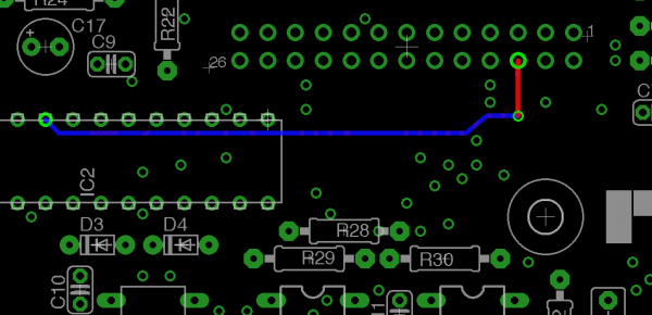
| ryktnk wrote: | | Please check the tracks on the Main PCB for the connection of this voltage |
I'm measuring the same voltages as across R19 on the via and the pin of IC2. Sadly it appears the resistance across that pin and gnd without panel is 126R3; seems like I managed to bugger that one as well.  |
|
|
Back to top
|
|
|
ryktnk
Joined: Apr 24, 2008
Posts: 285
Location: london
Audio files: 1
|
| Posted: Tue Jun 16, 2020 12:47 pm Post subject:
|
|
|
| nativeVS wrote: | | ryktnk wrote: | | Please check the tracks on the Main PCB for the connection of this voltage |
I'm measuring the same voltages as across R19 on the via and the pin of IC2. Sadly it appears the resistance across that pin and gnd without panel is 126R3; seems like I managed to bugger that one as well. |
Hello
Can you remove [ very carefully ] the PIC chip, and measure again the resistance from the previous highlighted PIN [ on the Pin header of the Main PCB ] to GND.
ryk |
|
|
Back to top
|
|
|
nativeVS
Joined: Dec 12, 2017
Posts: 14
Location: London
|
| Posted: Thu Jun 18, 2020 11:12 am Post subject:
|
|
|
| ryktnk wrote: | | measure again the resistance from the previous highlighted PIN [ on the Pin header of the Main PCB ] to GND. |
That's around 206k with the panel PCB connected. |
|
|
Back to top
|
|
|
Spelunker
Joined: Jun 19, 2020
Posts: 7
Location: Finland
|
| Posted: Fri Jun 19, 2020 1:13 am Post subject:
|
|
|
Hi, finished my M-185 build.
There is small weirdness however. I have only doepfer DIY kit power (1200ma +12, 1200ma -12v) if I remove all other modules and leave only M-185 it starts probably once in three restarts. When I connect it with other modules M-185 never boots up (other modules work fine) , unless I do ON -> OFF -> then very rapid ON again. Maybe because there is charge in capacitors and those together with fast power off -> on is enough to start module. When it starts however, everything works fine.
Does M-185 take lot's of power during startup and my Doepfer cannot supply it or is there something I screwed when I build module.. or maybe my Doepfer power has problems, unstable power at startup or something ? |
|
|
Back to top
|
|
|
ryktnk
Joined: Apr 24, 2008
Posts: 285
Location: london
Audio files: 1
|
| Posted: Fri Jun 19, 2020 1:15 am Post subject:
|
|
|
| nativeVS wrote: | | ryktnk wrote: | | measure again the resistance from the previous highlighted PIN [ on the Pin header of the Main PCB ] to GND. |
That's around 206k with the panel PCB connected. |
Hello
Thanks for the reading.
Sounds like you may have fried, or have a defective PIC.
Can you PM your details, and I can send you a replacement.
ryk |
|
|
Back to top
|
|
|
ryktnk
Joined: Apr 24, 2008
Posts: 285
Location: london
Audio files: 1
|
| Posted: Fri Jun 19, 2020 1:26 am Post subject:
|
|
|
| Spelunker wrote: | Hi, finished my M-185 build.
There is small weirdness however. I have only doepfer DIY kit power (1200ma +12, 1200ma -12v) if I remove all other modules and leave only M-185 it starts probably once in three restarts. When I connect it with other modules M-185 never boots up (other modules work fine) , unless I do ON -> OFF -> then very rapid ON again. Maybe because there is charge in capacitors and those together with fast power off -> on is enough to start module. When it starts however, everything works fine.
Does M-185 take lot's of power during startup and my Doepfer cannot supply it or is there something I screwed when I build module.. or maybe my Doepfer power has problems, unstable power at startup or something ? |
Hello
There should be plenty of power from your Doepfer, the M185 only uses
approx 85-110mA [ depending on how many LEDs are lit ]
Can you use a multimeter to check how much current [ + and - ] the M185 is drawing when connected to your Doepfer power supply.
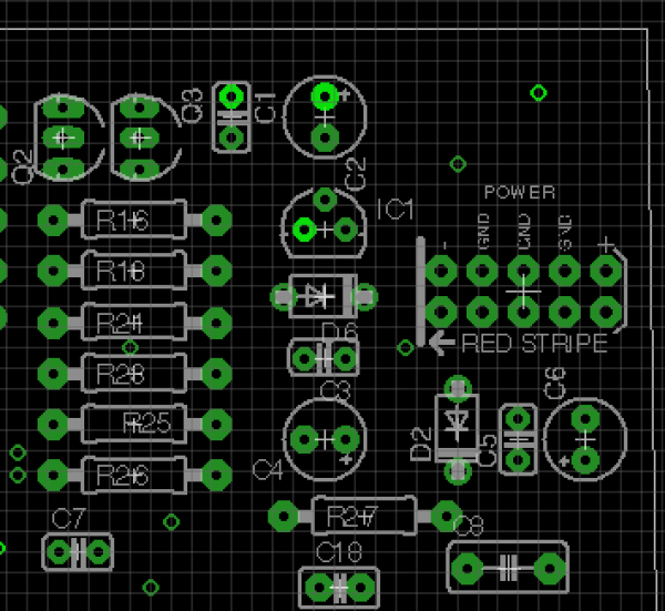
You can do this by measuring the current across the 1N5819 diodes [ D2,D6 ]
when the module is powered up.
If you are unsure how to do this, please ask first, to avoid any power supply accidents . . . . 
ryk |
|
|
Back to top
|
|
|
Spelunker
Joined: Jun 19, 2020
Posts: 7
Location: Finland
|
| Posted: Fri Jun 19, 2020 2:29 am Post subject:
|
|
|
| ryktnk wrote: | | Spelunker wrote: | Hi, finished my M-185 build.
There is small weirdness however. I have only doepfer DIY kit power (1200ma +12, 1200ma -12v) if I remove all other modules and leave only M-185 it starts probably once in three restarts. When I connect it with other modules M-185 never boots up (other modules work fine) , unless I do ON -> OFF -> then very rapid ON again. Maybe because there is charge in capacitors and those together with fast power off -> on is enough to start module. When it starts however, everything works fine.
Does M-185 take lot's of power during startup and my Doepfer cannot supply it or is there something I screwed when I build module.. or maybe my Doepfer power has problems, unstable power at startup or something ? |
Hello
There should be plenty of power from your Doepfer, the M185 only uses
approx 85-110mA [ depending on how many LEDs are lit ]
Can you use a multimeter to check how much current [ + and - ] the M185 is drawing when connected to your Doepfer power supply.
You can do this by measuring the current across the 1N5819 diodes [ D2,D6 ]
when the module is powered up.
If you are unsure how to do this, please ask first, to avoid any power supply accidents . . . .
ryk |
I did small protoboard testrig to "break" powercable and measure current.
When module succesfully powers up:
80-82mA +12v
12mA -12v
when it does not power up:
totally random 53mA - 180mA from +12v depending on power on cycle, it does not jump around. When I power up, it may stay on that 53mA or another power on cycle it may stay 70mA. Just once it was 180mA, usually around 53mA or 70mA.
-12v stays on 12mA like on succesfull power up. |
|
|
Back to top
|
|
|
ryktnk
Joined: Apr 24, 2008
Posts: 285
Location: london
Audio files: 1
|
| Posted: Fri Jun 19, 2020 5:41 am Post subject:
|
|
|
| Spelunker wrote: | | ryktnk wrote: | | Spelunker wrote: | Hi, finished my M-185 build.
There is small weirdness however. I have only doepfer DIY kit power (1200ma +12, 1200ma -12v) if I remove all other modules and leave only M-185 it starts probably once in three restarts. When I connect it with other modules M-185 never boots up (other modules work fine) , unless I do ON -> OFF -> then very rapid ON again. Maybe because there is charge in capacitors and those together with fast power off -> on is enough to start module. When it starts however, everything works fine.
Does M-185 take lot's of power during startup and my Doepfer cannot supply it or is there something I screwed when I build module.. or maybe my Doepfer power has problems, unstable power at startup or something ? |
Hello
There should be plenty of power from your Doepfer, the M185 only uses
approx 85-110mA [ depending on how many LEDs are lit ]
Can you use a multimeter to check how much current [ + and - ] the M185 is drawing when connected to your Doepfer power supply.
You can do this by measuring the current across the 1N5819 diodes [ D2,D6 ]
when the module is powered up.
If you are unsure how to do this, please ask first, to avoid any power supply accidents . . . .
ryk |
I did small protoboard testrig to "break" powercable and measure current.
When module succesfully powers up:
80-82mA +12v
12mA -12v
when it does not power up:
totally random 53mA - 180mA from +12v depending on power on cycle, it does not jump around. When I power up, it may stay on that 53mA or another power on cycle it may stay 70mA. Just once it was 180mA, usually around 53mA or 70mA.
-12v stays on 12mA like on succesfull power up. |
Sounds pretty strange.
When the module powers successfully, are all the functions working ok ?
Can you repeat the test without the Panel PCB connected.
Please check carefully all the soldering around IC1 and IC100, these are the power
regulators.
Also the orientation of capacitors C1,C4,C6 |
|
|
Back to top
|
|
|
Spelunker
Joined: Jun 19, 2020
Posts: 7
Location: Finland
|
| Posted: Fri Jun 19, 2020 8:51 am Post subject:
|
|
|
| ryktnk wrote: |
Sounds pretty strange.
When the module powers successfully, are all the functions working ok ?
Can you repeat the test without the Panel PCB connected.
Please check carefully all the soldering around IC1 and IC100, these are the power
regulators.
Also the orientation of capacitors C1,C4,C6 |
Yep, when module powers up everything works. I calibrated both cv channels, no problems there, every switch works etc..
Without Panel PCB +12v current draw is sometimes 70mA and sometimes it is only 55mA
Orientation of all electrolytics is ok and there does not seem to be any obvious problems with solder. |
|
|
Back to top
|
|
|
ryktnk
Joined: Apr 24, 2008
Posts: 285
Location: london
Audio files: 1
|
| Posted: Sat Jun 20, 2020 2:44 pm Post subject:
|
|
|
| Spelunker wrote: | | ryktnk wrote: |
Sounds pretty strange.
When the module powers successfully, are all the functions working ok ?
Can you repeat the test without the Panel PCB connected.
Please check carefully all the soldering around IC1 and IC100, these are the power
regulators.
Also the orientation of capacitors C1,C4,C6 |
Yep, when module powers up everything works. I calibrated both cv channels, no problems there, every switch works etc..
Without Panel PCB +12v current draw is sometimes 70mA and sometimes it is only 55mA
Orientation of all electrolytics is ok and there does not seem to be any obvious problems with solder. |
What happens when the module doesnt power up ?
Any lights, any clock output, etc ? |
|
|
Back to top
|
|
|
Spelunker
Joined: Jun 19, 2020
Posts: 7
Location: Finland
|
| Posted: Sun Jun 21, 2020 7:02 am Post subject:
|
|
|
| ryktnk wrote: |
What happens when the module doesnt power up ?
Any lights, any clock output, etc ? |
No lights, not even flash at startup, button pressed does not change anything. CV out gives some random voltage that is slowly rising OR falling, like 1.18V that is increasing 0.01V per sec. Or 2.8v that is decreasing 0.01v per sec. |
|
|
Back to top
|
|
|
ryktnk
Joined: Apr 24, 2008
Posts: 285
Location: london
Audio files: 1
|
|
|
Back to top
|
|
|
Spelunker
Joined: Jun 19, 2020
Posts: 7
Location: Finland
|
| Posted: Thu Jun 25, 2020 7:49 am Post subject:
|
|
|
| ryktnk wrote: |
Can you measure the voltage regulators when you switch on.
IC1 & IC100
See pic for highlighted pins. |
Those pins show 4,96v. When working or when not working...
IC1 and IC100. |
|
|
Back to top
|
|
|
ryktnk
Joined: Apr 24, 2008
Posts: 285
Location: london
Audio files: 1
|
| Posted: Sat Jun 27, 2020 4:11 am Post subject:
|
|
|
| Spelunker wrote: | | ryktnk wrote: |
Can you measure the voltage regulators when you switch on.
IC1 & IC100
See pic for highlighted pins. |
Those pins show 4,96v. When working or when not working...
IC1 and IC100. |
Hello
Thanks, voltages sound ok.
Sounds like something weird happening with the PIC chip.
Can you measure the following voltages on the PIC; IC2 . [ Main PCB ]
Between PIN 8 [ black probe ] PIN 20 [ red probe ]
Between PIN 19 [ black probe ] PIN 20 [ red probe ]
Can you power up normally, and try and get a non-sucessful power up status[ no lights ]
Then turn the Tempo to max, and check if there is any clock output on the Clock IO. [ plug into known working gat/env module etc]
The seq normally boots up with the clock running.
If nothing, press the Start stop button [grey ]once, check again, press again once, check again.
If nothring, then perhaps the PIC chip is damaged.
PM your details and I can send a replacement.
ryk |
|
|
Back to top
|
|
|
nativeVS
Joined: Dec 12, 2017
Posts: 14
Location: London
|
| Posted: Sat Jun 27, 2020 9:24 am Post subject:
All Working |
|
|
Hi ryk,
thanks for sending the replacement PIC; it's all happy now and working without problems. Cheers.
Robert |
|
|
Back to top
|
|
|
ryktnk
Joined: Apr 24, 2008
Posts: 285
Location: london
Audio files: 1
|
| Posted: Mon Jun 29, 2020 12:33 pm Post subject:
Re: All Working |
|
|
| nativeVS wrote: | Hi ryk,
thanks for sending the replacement PIC; it's all happy now and working without problems. Cheers.
Robert |
Great !  |
|
|
Back to top
|
|
|
Spelunker
Joined: Jun 19, 2020
Posts: 7
Location: Finland
|
| Posted: Mon Jul 06, 2020 7:06 am Post subject:
|
|
|
| ryktnk wrote: |
Hello
Thanks, voltages sound ok.
Sounds like something weird happening with the PIC chip.
Can you measure the following voltages on the PIC; IC2 . [ Main PCB ]
Between PIN 8 [ black probe ] PIN 20 [ red probe ]
Between PIN 19 [ black probe ] PIN 20 [ red probe ]
Can you power up normally, and try and get a non-sucessful power up status[ no lights ]
Then turn the Tempo to max, and check if there is any clock output on the Clock IO. [ plug into known working gat/env module etc]
The seq normally boots up with the clock running.
If nothing, press the Start stop button [grey ]once, check again, press again once, check again.
If nothring, then perhaps the PIC chip is damaged.
PM your details and I can send a replacement.
ryk |
Hello,
Took some time as I was away from studio.
Anyway I picked up new power (Behringer CP1A) and after lots of repeats I simply cannot recreate this bug with Behringer power. M185 seem to work as expected on every power up 
So.. I believe there is something broken on my Doepfer power.
It gives stable +12/-12 according to my multimeter but maybe there is low/high/unstable voltages right after power up so M185's PIC goes to some weird faulty state. As I do not have oscilloscope it is hard to debug this further.
Thank You for passionate debugging! |
|
|
Back to top
|
|
|
ryktnk
Joined: Apr 24, 2008
Posts: 285
Location: london
Audio files: 1
|
| Posted: Tue Jul 07, 2020 2:37 am Post subject:
|
|
|
| Spelunker wrote: |
Hello,
Took some time as I was away from studio.
Anyway I picked up new power (Behringer CP1A) and after lots of repeats I simply cannot recreate this bug with Behringer power. M185 seem to work as expected on every power up
So.. I believe there is something broken on my Doepfer power.
It gives stable +12/-12 according to my multimeter but maybe there is low/high/unstable voltages right after power up so M185's PIC goes to some weird faulty state. As I do not have oscilloscope it is hard to debug this further.
Thank You for passionate debugging! |
Hello
Thats good news all is working.
But a bit mysterious/worrying about the Doepfer supply . . .
Which model is it, and also roughly which manufacture date/purchase date ?
ryk |
|
|
Back to top
|
|
|
Spelunker
Joined: Jun 19, 2020
Posts: 7
Location: Finland
|
| Posted: Thu Jul 16, 2020 10:26 am Post subject:
|
|
|
| ryktnk wrote: |
Hello
Thats good news all is working.
But a bit mysterious/worrying about the Doepfer supply . . .
Which model is it, and also roughly which manufacture date/purchase date ?
ryk |
It's Doepfer A-100 DIY kit power and it is old, I bought it 2016.
http://www.doepfer.de/a100_DIY_kits.htm |
|
|
Back to top
|
|
|
Muramasa
Joined: May 01, 2019
Posts: 1
Location: Scotland
|
| Posted: Sat Jul 25, 2020 9:45 pm Post subject:
|
|
|
| Is there any plans for a buchla version? |
|
|
Back to top
|
|
|
ryktnk
Joined: Apr 24, 2008
Posts: 285
Location: london
Audio files: 1
|
| Posted: Thu Jul 30, 2020 7:12 am Post subject:
|
|
|
| Muramasa wrote: | | Is there any plans for a buchla version? |
None at the moment. |
|
|
Back to top
|
|
|
|

 Forum index » DIY Hardware and Software