| Author |
Message |
haxster
Joined: Feb 01, 2006
Posts: 246
Location: MONTEREY PARK, CA 91754
G2 patch files: 2
|
|
|
Back to top
|
|
 |
Luka

Joined: Jun 29, 2007
Posts: 1003
Location: Melb.
|
|
|
Back to top
|
|
 |
haxster
Joined: Feb 01, 2006
Posts: 246
Location: MONTEREY PARK, CA 91754
G2 patch files: 2
|
 Posted: Sat Jun 27, 2009 10:31 pm Post subject: Posted: Sat Jun 27, 2009 10:31 pm Post subject:
|
  |
|
| Yeah, I have to do that. I will post soon. I just got express PCB schamtic all setup for my needs to make it faster. |
|
|
Back to top
|
|
 |
a100user

Joined: Oct 28, 2003
Posts: 158
Location: UK
|
 Posted: Mon Jun 29, 2009 1:01 am Post subject: Posted: Mon Jun 29, 2009 1:01 am Post subject:
|
  |
|
Hi Haxster,
Board and PIC has arrived.
many thanks
David |
|
|
Back to top
|
|
 |
haxster
Joined: Feb 01, 2006
Posts: 246
Location: MONTEREY PARK, CA 91754
G2 patch files: 2
|
 Posted: Tue Jun 30, 2009 10:53 am Post subject: Posted: Tue Jun 30, 2009 10:53 am Post subject:
|
  |
|
Here's the schematic for the DVCLFO core.
| Description: |
|

Download (listen) |
| Filename: |
REV1.2_PAGE1.bmp |
| Filesize: |
866.31 KB |
| Downloaded: |
441 Time(s) |
| Description: |
|

Download (listen) |
| Filename: |
REV1.2_PAGE2.bmp |
| Filesize: |
866.31 KB |
| Downloaded: |
408 Time(s) |
|
|
|
Back to top
|
|
 |
Luka

Joined: Jun 29, 2007
Posts: 1003
Location: Melb.
|
|
|
Back to top
|
|
 |
jojjelito
Joined: Jun 27, 2007
Posts: 50
Location: Stockholm, Sweden
|
 Posted: Mon Jul 13, 2009 1:57 pm Post subject: Posted: Mon Jul 13, 2009 1:57 pm Post subject:
|
  |
|
| Drats! Missed out on both runs... Any chance of a new one? I would be in for at least 2 boards with PICs if that came to pass. |
|
|
Back to top
|
|
 |
henrikgo
Joined: Jul 05, 2008
Posts: 40
Location: sweden
|
 Posted: Sun Jan 10, 2010 9:20 am Post subject: Posted: Sun Jan 10, 2010 9:20 am Post subject:
|
  |
|
I'm about to finish up my LFO but there are a couple of caps that I can't find the value for. The ones marked with red.
 |
|
|
Back to top
|
|
 |
haxster
Joined: Feb 01, 2006
Posts: 246
Location: MONTEREY PARK, CA 91754
G2 patch files: 2
|
 Posted: Sun Jan 10, 2010 4:28 pm Post subject: Posted: Sun Jan 10, 2010 4:28 pm Post subject:
|
  |
|
The one at the bottom is 0.1uf, that is for the GLIDE/portamento
The two Cap pairs are for the Analog LFO's. Pair them with values like this: 0.0047uf, 0.01uf. You are free to experient with values. The higher the cap the slower the LFO. For example 2UF NP will make it go really slow.
A good combo is like this: 0.00xx uF, 0.0x uF.
The Last one circled in red is an LED not a cap. |
|
|
Back to top
|
|
 |
Luka

Joined: Jun 29, 2007
Posts: 1003
Location: Melb.
|
|
|
Back to top
|
|
 |
henrikgo
Joined: Jul 05, 2008
Posts: 40
Location: sweden
|
 Posted: Sun Mar 21, 2010 6:57 am Post subject: Posted: Sun Mar 21, 2010 6:57 am Post subject:
|
  |
|
| haxster wrote: | The one at the bottom is 0.1uf, that is for the GLIDE/portamento
The two Cap pairs are for the Analog LFO's. Pair them with values like this: 0.0047uf, 0.01uf. You are free to experient with values. The higher the cap the slower the LFO. For example 2UF NP will make it go really slow.
A good combo is like this: 0.00xx uF, 0.0x uF.
The Last one circled in red is an LED not a cap. |
Thanks! I actually didn't get around to finish it when I asked, so one more question the Cap pairs for the Analog LFO's is the higher value Cap the ones closest to the TL074? |
|
|
Back to top
|
|
 |
sduck

Joined: Dec 16, 2007
Posts: 459
Location: Nashville
Audio files: 5
|
 Posted: Sun Mar 21, 2010 5:47 pm Post subject: Posted: Sun Mar 21, 2010 5:47 pm Post subject:
|
  |
|
| I've got a pcb/pic set of this that I'm probably never going to get around to using - it's way down on the bottom of a huge stack of things that want to get built first. So realistically I should let them go to whoever wants them, for the 40$ US that I paid for them. These are from the first run. PM me. |
|
|
Back to top
|
|
 |
Luka

Joined: Jun 29, 2007
Posts: 1003
Location: Melb.
|
 Posted: Sun Mar 21, 2010 9:39 pm Post subject: Posted: Sun Mar 21, 2010 9:39 pm Post subject:
|
  |
|
shame about that
i think this is an awesome design
phase distortion lfo!!
it is a shame it doesnt go into vco ranges
im going to make a mod pcb to get all the options out of the PIC too
_________________
problemchild
melbourne australia
http://cycleofproblems.blogspot.com/
http://www.last.fm/user/prblmchild |
|
|
Back to top
|
|
 |
haxster
Joined: Feb 01, 2006
Posts: 246
Location: MONTEREY PARK, CA 91754
G2 patch files: 2
|
 Posted: Thu Mar 25, 2010 5:03 pm Post subject: Posted: Thu Mar 25, 2010 5:03 pm Post subject:
|
  |
|
| henrikgo wrote: | | haxster wrote: | The one at the bottom is 0.1uf, that is for the GLIDE/portamento
The two Cap pairs are for the Analog LFO's. Pair them with values like this: 0.0047uf, 0.01uf. You are free to experient with values. The higher the cap the slower the LFO. For example 2UF NP will make it go really slow.
A good combo is like this: 0.00xx uF, 0.0x uF.
The Last one circled in red is an LED not a cap. |
Thanks! I actually didn't get around to finish it when I asked, so one more question the Cap pairs for the Analog LFO's is the higher value Cap the ones closest to the TL074? |
The cap values and where they go is not critical. The switch would toggle between them any how. So for example if I say the Higher value is the one Closest to the TL074. You can always flip your Switch on the panel if you prefer it your way. |
|
|
Back to top
|
|
 |
Luka

Joined: Jun 29, 2007
Posts: 1003
Location: Melb.
|
 Posted: Sat Apr 10, 2010 5:49 pm Post subject: Posted: Sat Apr 10, 2010 5:49 pm Post subject:
|
  |
|
haxster
did you use this schem for the analog lfo?

i cant seem to get the square / ramp switch working
can you provide a wiring diagram for this for me
it is hard to know what is going on with no real schematic
_________________
problemchild
melbourne australia
http://cycleofproblems.blogspot.com/
http://www.last.fm/user/prblmchild |
|
|
Back to top
|
|
 |
haxster
Joined: Feb 01, 2006
Posts: 246
Location: MONTEREY PARK, CA 91754
G2 patch files: 2
|
 Posted: Sat Apr 10, 2010 6:14 pm Post subject: Posted: Sat Apr 10, 2010 6:14 pm Post subject:
|
  |
|
| Yeah I used that circuit, I will open up the file and help you out. I am not home right now, I will do it when I get home. |
|
|
Back to top
|
|
 |
Luka

Joined: Jun 29, 2007
Posts: 1003
Location: Melb.
|
|
|
Back to top
|
|
 |
haxster
Joined: Feb 01, 2006
Posts: 246
Location: MONTEREY PARK, CA 91754
G2 patch files: 2
|
 Posted: Mon Apr 12, 2010 10:26 am Post subject: Posted: Mon Apr 12, 2010 10:26 am Post subject:
|
  |
|
| Oh wait I used the Soundlab Plus LFO not the Ultimate. I will have info soon. |
|
|
Back to top
|
|
 |
Luka

Joined: Jun 29, 2007
Posts: 1003
Location: Melb.
|
 Posted: Tue Apr 13, 2010 3:24 pm Post subject: Posted: Tue Apr 13, 2010 3:24 pm Post subject:
|
  |
|
i finally found the schematic for sl-plus lfo
there is no link for it on the mfos site anywhere but luckily the page is still there and i was able to find a link to it on a forum thread

_________________
problemchild
melbourne australia
http://cycleofproblems.blogspot.com/
http://www.last.fm/user/prblmchild |
|
|
Back to top
|
|
 |
haxster
Joined: Feb 01, 2006
Posts: 246
Location: MONTEREY PARK, CA 91754
G2 patch files: 2
|
 Posted: Tue Apr 13, 2010 11:44 pm Post subject: Posted: Tue Apr 13, 2010 11:44 pm Post subject:
|
  |
|
| Did you figure it out yet or do you still have trouble? If I recall on the first run, the Analog LFO has the 1 2 3 labeled wrong I think i mentioned this on the previous page. |
|
|
Back to top
|
|
 |
Luka

Joined: Jun 29, 2007
Posts: 1003
Location: Melb.
|
 Posted: Wed Apr 14, 2010 1:15 am Post subject: Posted: Wed Apr 14, 2010 1:15 am Post subject:
|
  |
|
my pcbs were from 2nd batch
i think i have got it now, yet to test
ive been working on my mods to the digital lfo today but ill test this again now
the problem was i had no idea how those numbers match the switch pins
even now that i have an idea of how to route the wires the numbers dont make sense to me
how can 1 and 4 mean the center pins of the switch?
is this correct?
i usually think that dpdt switches are like this
1 4
2 5
3 6
where as i think you have it like this
2 5
1 4
3 6
_________________
problemchild
melbourne australia
http://cycleofproblems.blogspot.com/
http://www.last.fm/user/prblmchild
Last edited by Luka on Wed Apr 14, 2010 1:22 am; edited 1 time in total |
|
|
Back to top
|
|
 |
haxster
Joined: Feb 01, 2006
Posts: 246
Location: MONTEREY PARK, CA 91754
G2 patch files: 2
|
 Posted: Wed Apr 14, 2010 1:22 am Post subject: Posted: Wed Apr 14, 2010 1:22 am Post subject:
|
  |
|
It's like this:
1 is the center, then 2 is above, then 3 is below (that's one column)
2
1
3
next 4 is the center, then 5 is above, then 6 is below (that's one column)
5
4
6 |
|
|
Back to top
|
|
 |
Luka

Joined: Jun 29, 2007
Posts: 1003
Location: Melb.
|
|
|
Back to top
|
|
 |
Luka

Joined: Jun 29, 2007
Posts: 1003
Location: Melb.
|
|
|
Back to top
|
|
 |
Luka

Joined: Jun 29, 2007
Posts: 1003
Location: Melb.
|
 Posted: Mon May 10, 2010 5:42 am Post subject: Posted: Mon May 10, 2010 5:42 am Post subject:
|
  |
|
so has anyone built their lfos?
i have finally got mine completed
the squarewave on the analog lfo was running rail to rail (30vpp)
i used a simple voltage divider (49k9/27k) to get it down to 10vpp
i also implemented vc-sample'n'hold, vc-waveform selection, vc-phase distortion
took a lot of work to get it going but it was worth it
im doing the 2nd one now
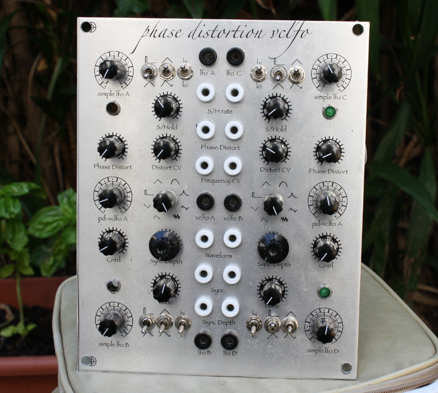
here is the panel

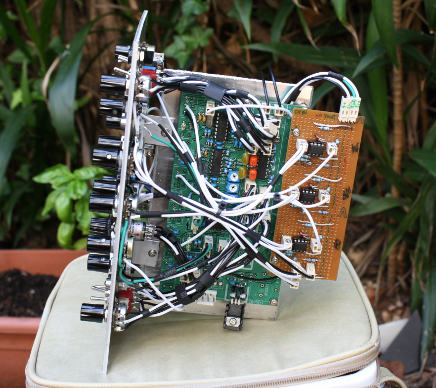
and the mess

_________________
problemchild
melbourne australia
http://cycleofproblems.blogspot.com/
http://www.last.fm/user/prblmchild |
|
|
Back to top
|
|
 |
|

