| Author |
Message |
dylar
Joined: Apr 25, 2011
Posts: 55
Location: iowa
|
 Posted: Fri Feb 08, 2013 7:29 pm Post subject: Posted: Fri Feb 08, 2013 7:29 pm Post subject:
|
  |
|
| So no one has come up with a working schematic for the input jack yet? PLEASE someone help... |
|
|
Back to top
|
|
 |
elmegil

Joined: Mar 20, 2012
Posts: 2179
Location: Chicago
Audio files: 16
|
| Posted: Sat Feb 09, 2013 12:12 am Post subject:
|
|
|
I built the basic cacophonator circuit over the last hour (sounds really cool), and I will work on the audio input some time tomorrow or Sunday.
One thing I noticed that may be important--I haven't read this thread in detail, but I was thinking I needed to use a 4069 for the audio input, as that seemed to be the main thing people were talking about where I was skimming. However, the circuit diagram from page 4 uses a 4049, which has a very different pinout... I would guess if you used a 4069 but connected the pins as shown in the schematic, things would not go well for the audio input. I will try both (with appropriate pin changes) and see if one does better than the other.
One other difference in mine is that I'm using a 15V bench supply rather than a 9V battery for power, but for the basic circuit that doesn't seem to make a lot of difference. |
|
|
Back to top
|
|
|
elmegil
Joined: Mar 20, 2012
Posts: 2179
Location: Chicago
Audio files: 16
|
| Posted: Sat Feb 09, 2013 9:17 am Post subject:
|
|
|
Built the audio in, heard no effect. Shifted my jack to before C13, and BARELY heard my audio--my input is a smartphone because I'm monitoring through my computer.
I believe I need some amplification of my source signal before this might work, not sure if that's relevant to anyone who was working on this before or not. I'm going to set up a little LM386 pre amp stage and see if that works any better. |
|
|
Back to top
|
|
|
dylar
Joined: Apr 25, 2011
Posts: 55
Location: iowa
|
| Posted: Sat Feb 09, 2013 4:06 pm Post subject:
|
|
|
Thanks for the effort! Excited to hear about your results.
| elmegil wrote: | Built the audio in, heard no effect. Shifted my jack to before C13, and BARELY heard my audio--my input is a smartphone because I'm monitoring through my computer.
I believe I need some amplification of my source signal before this might work, not sure if that's relevant to anyone who was working on this before or not. I'm going to set up a little LM386 pre amp stage and see if that works any better. |
|
|
|
Back to top
|
|
|
elmegil
Joined: Mar 20, 2012
Posts: 2179
Location: Chicago
Audio files: 16
|
| Posted: Sun Feb 10, 2013 12:39 pm Post subject:
|
|
|
Amplification does get the signal through, but it doesn't sound to me like the video, it just basically mixes the audio through. No variable distortion, it's either there and competing with the oscillators, or it's not. The frequency of the oscillators/starvation of the circuit are the only things that affect how much distortion there is on the signal, not gain on the LM386, and not the pot on either the 4069 or Oscillator 4 (where it gets injected).
If anyone else wants to try it, I used the amp circuit from here:
http://www.fluxmonkey.com/electronoize/386amplifier.htm |
|
|
Back to top
|
|
|
dylar
Joined: Apr 25, 2011
Posts: 55
Location: iowa
|
| Posted: Sun Feb 10, 2013 11:38 pm Post subject:
|
|
|
I'm getting suspicious about the whole project. As far as I can tell the only video of a Cacophonator that actually processes a signal is the Sascha Neudeck one. There are two other versions with inputs, neither of which actually distorts the signal (or if it does it's very subtle):
http://youtu.be/11ObmwNxL7U
http://youtu.be/zURxDI_QQHk
After watching Neudeck's video again I think I know what is going on. First, there are two extra knobs on his. I'm guessing he added a simple LP filter (and maybe something else) in between the audio input and the output. When he's turning the two knobs on the bottom left he's operating the added effects. The other knobs just seem to adjust the normal cacophonator squeal. When you have the noise made by the cacophonator along with and input signal that passes through a filter and maybe distortion circuit then you'd get sounds like you get in his video. It's possible that the cacophonator also passes through the filter--I can't tell. Maybe the second mystery knob adjusts the input level or else a distortion level. Here's his video:
http://www.youtube.com/watch?v=q_s4U-8V2Gg&feature=share&list=PL416C4854F84E5312
It's actually pretty brilliant. It probably doesn't work too well with guitar. |
|
|
Back to top
|
|
|
synthesist
Joined: Feb 17, 2011
Posts: 79
Location: austria
Audio files: 2
|
| Posted: Fri Feb 15, 2013 11:34 am Post subject:
|
|
|
After some problems I finally build some versions with working input.
But I never kept the circuit on breadboard cause it didnt sound good enough.
The best result I ever had was to play the output of the atari punk console into Pin 14 without any amplification. It worked like one could use the cacophonator like an broken equalizer distortion resonator. really cool.
I am sure the input has to be only Pin 14 where the chip gets it voltage. Otherwise I think u would destroy the unit. If the chip doestnt get enough voltage but the inverters do ( because of the high amplificatioon) it is supposed to die!
U guyes should filter the amplified output before it goes to pin 14. Just try different capacitors against ground. This makes it sound better.
goog luck
xonrad |
|
|
Back to top
|
|
|
Familiar
Joined: May 14, 2013
Posts: 2
Location: Barcelona
|
|
|
Back to top
|
|
|
egasimus

Joined: Feb 11, 2011
Posts: 113
Location: Bulgaria
|
| Posted: Thu Jul 25, 2013 5:19 am Post subject:
|
|
|
| ^ awesome stuff! I'll build that. Care to share more info on the Quad-T conga? |
|
|
Back to top
|
|
|
Familiar
Joined: May 14, 2013
Posts: 2
Location: Barcelona
|
|
|
Back to top
|
|
|
AlasdairMoons

Joined: Dec 03, 2011
Posts: 105
Location: East-Belgium
|
|
|
Back to top
|
|
|
umschmitt

Joined: Jun 29, 2011
Posts: 189
Location: brrlin
Audio files: 11
|
| Posted: Tue Jan 28, 2014 2:38 pm Post subject:
|
|
|
Hi all!
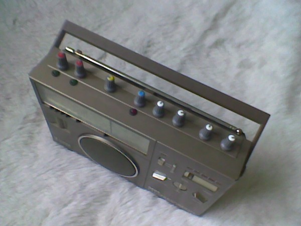
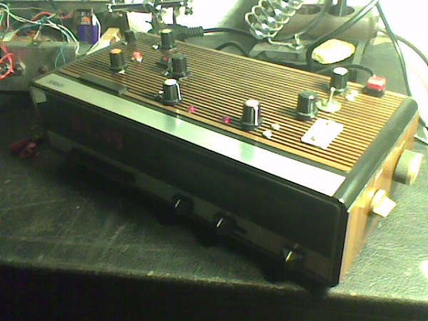
I thought I'd share my take on the Cacophonator… It's a somewhat upgraded version with switches to allow chain sync between oscs, contact points (or whatever you call them), an LDR for kicks and also the possibility to somehow sync osc#1 to an external signal or… the sound of the radio.
Because, yes it's build in an (otherwise fully functional) alarm clock. Of course you can also use the internal speaker for a nomadic use… but wait! err it works on the mains! Oh well.
Bonuses: once you plug and start to play, the display will show you how long you've been messing with the thang. Alternatively you can program the 'sleep' function if you want to play, say 34 minutes and forget about time. It'll shut off from itself. How cool is that? How useless also?
It also looks miserable. Let's say it's a whole concept, eheh. Should I mention that it's exclusively made out of salvaged parts? (well the 40106 was new)
Anyway, here's a pic - ©crappy cellphone - and a couple sound clips…
| Description: |
|
| Filesize: |
83.15 KB |
| Viewed: |
1093 Time(s) |
| This image has been reduced to fit the page. Click on it to enlarge. |
|
| Description: |
| The usual cacophonic orchestra. |
|

Download (listen) |
| Filename: |
schrottophonator3.ogg |
| Filesize: |
2.6 MB |
| Downloaded: |
1712 Time(s) |
| Description: |
| Some kind of power drones here (with substantial amounts of Realistic© reverb fed back - which is neither realistic, nor even a reverb!). |
|
Download (listen) |
| Filename: |
schrottophonator2.ogg |
| Filesize: |
4.95 MB |
| Downloaded: |
1710 Time(s) |
| Description: |
| Surprisingly musical chaos. How's that just possible? |
|
Download (listen) |
| Filename: |
schrottophonator1.ogg |
| Filesize: |
785.59 KB |
| Downloaded: |
1701 Time(s) |
_________________
::U::N::S::C::H::N::E::L::L:: |
|
|
Back to top
|
|
|
DUBmatze

Joined: Feb 18, 2013
Posts: 150
Location: south Germaica (schwabilon)
|
| Posted: Tue Jan 28, 2014 4:41 pm Post subject:
|
|
|
geiles Ding !!
nice demo, nice "timer" function!
 |
|
|
Back to top
|
|
|
PHOBoS

Joined: Jan 14, 2010
Posts: 5950
Location: Moon Base
Audio files: 709
|
|
|
Back to top
|
|
|
umschmitt
Joined: Jun 29, 2011
Posts: 189
Location: brrlin
Audio files: 11
|
| Posted: Fri Jan 31, 2014 7:05 am Post subject:
|
|
|
Thanks! It will be proposed locally next week among other items in a solidarity auction.
You've been warned.
_________________
::U::N::S::C::H::N::E::L::L:: |
|
|
Back to top
|
|
|
umschmitt
Joined: Jun 29, 2011
Posts: 189
Location: brrlin
Audio files: 11
|
| Posted: Wed Feb 12, 2014 5:47 am Post subject:
|
|
|
Update: the schrottophonator sold for a good 65 euros. No idea if it's a lot or not, anyway the money was welcome for the cause. And lots of people had fun playing it the whole evening.
_________________
::U::N::S::C::H::N::E::L::L:: |
|
|
Back to top
|
|
|
Speedy RB

Joined: Apr 02, 2013
Posts: 12
Location: SoCal, USA
|
| Posted: Thu Feb 13, 2014 12:11 am Post subject:
|
|
|
I finally built this puppy based on your cool antique layout, -minus-, thanks again!
One question: RV7 doesn't seem to do much of anything. Every once in a while, depending upon the positions of RV5 and RV6, maybe I notice something happening, but for the most part, nada. I've even switched out the pot to make sure it wasn't faulty.
Is this expected, or did something go wrong with my build? Everything else behaves as expected.
Once I get it mounted maybe I'll post some pics... |
|
|
Back to top
|
|
|
-minus-
Joined: Oct 26, 2008
Posts: 787
Audio files: 13
|
| Posted: Thu Feb 13, 2014 12:45 am Post subject:
|
|
|
As far as I recall, all the pots do something. I'd need to dig it out and do some tests though.
If all other pots do something, you are close to having it working. Check the stripboard cuts on the back of the board. Make sure the components around pin 12 and pin 13 are in the right place and soldered correctly. Also, there was an issue of me posting an incorrect image of the reverse side of the board originally. Make sure there is a cut in the stripboard rail above the IC. The present image on page one is correct.
It sounds like the oscillator on pin 12 and 13 isn't working. Check for solder bridges, cold solder joints, incorrect placement of components, incorrect component values perhaps. |
|
|
Back to top
|
|
|
Speedy RB
Joined: Apr 02, 2013
Posts: 12
Location: SoCal, USA
|
| Posted: Thu Feb 13, 2014 12:30 pm Post subject:
|
|
|
After a little poking around with a straightened paper clip, I did indeed find a cold solder joint on the pot. It looked totally fine, I've never had one of those before.
Thanks!
Also, I am going to add the input described for the "6DE" by familiar. Looks good!
Also also, -minus-, I saw this while researching the cacophonator+input:
http://befaco.org/forum/phpBB3/viewtopic.php?f=21&t=38&hilit=cacophonator+6de |
|
|
Back to top
|
|
|
elmegil
Joined: Mar 20, 2012
Posts: 2179
Location: Chicago
Audio files: 16
|
| Posted: Thu Feb 13, 2014 3:11 pm Post subject:
|
|
|
| Speedy RB wrote: | | After a little poking around with a straightened paper clip, I did indeed find a cold solder joint on the pot. It looked totally fine, I've never had one of those before. |
Can you describe your method of testing further? I'm not sure how that would work. Just looking for things that wiggle but shouldn't? |
|
|
Back to top
|
|
|
Speedy RB
Joined: Apr 02, 2013
Posts: 12
Location: SoCal, USA
|
| Posted: Thu Feb 13, 2014 3:19 pm Post subject:
|
|
|
| elmegil wrote: | | Speedy RB wrote: | | After a little poking around with a straightened paper clip, I did indeed find a cold solder joint on the pot. It looked totally fine, I've never had one of those before. |
Can you describe your method of testing further? I'm not sure how that would work. Just looking for things that wiggle but shouldn't? |
I used the paper clip to connect the two points on the board where the pot connects - in other words, as if the pot were dialed to 0 resistance - and immediately heard the sound change drastically. Then, by laying the paper clip across the joint between the wire and pin 1 of the pot, I heard the same change in sound, so I re-did that solder joint, and viola - the pot now works. |
|
|
Back to top
|
|
|
umschmitt
Joined: Jun 29, 2011
Posts: 189
Location: brrlin
Audio files: 11
|
|
|
Back to top
|
|
|
Nyxaudio
Joined: Jul 07, 2015
Posts: 7
Location: Nz
|
| Posted: Tue Jul 07, 2015 11:42 pm Post subject:
|
|
|
howdy
i have a couple questions regarding this build
i have not done this before so bear with me please
there are 4 wire connections made on the diagram? is this correct? or do c8 and c3 have them too?
also can i just connect the power supply to the holes on the top and second from top on the top left corner
Hope some one can please help me
thankyou in advance |
|
|
Back to top
|
|
|
-minus-
Joined: Oct 26, 2008
Posts: 787
Audio files: 13
|
| Posted: Wed Jul 08, 2015 2:05 am Post subject:
|
|
|
| I'd like to help you but I am unsure which diagram you are referring to. There seems to be a few layouts on this thread now. |
|
|
Back to top
|
|
|
Nyxaudio
Joined: Jul 07, 2015
Posts: 7
Location: Nz
|
|
|
Back to top
|
|
|
|

 Forum index » DIY Hardware and Software