| Author |
Message |
dnny

Joined: Mar 12, 2005
Posts: 519
Location: Helsinki, Finland
Audio files: 8
|
 Posted: Fri May 13, 2005 4:09 am Post subject:
DS 7 clone Posted: Fri May 13, 2005 4:09 am Post subject:
DS 7 clone
Subject description: CORON DS7 Drum Synce Clone. PCB + mods |
  |
|
Have you build the DS7-clone ?
well i did and its great.
| Quote: | | The DS7 contain a VCO +VCA chain. The VCO is modulated by a cheesy LFO and a simple decay envelope trigged by the piezzo cell pulse. |
and its super easy to build and cheap - perfect project for newbies and nice for those who has advanced in DIY
project can be found here :
http://m.bareille.free.fr/ds7clone/ds7.htm
here are some super simple mods
for "deeper" bass on VCO replace R11 (560ohm) whit 100ohm
if you want to ad external input for VCA , example for noise,
run wire from jack to leg 3 of CA3080 via 100k resistor
i have the pcb layout for three DS 7 in one 10cm x 16cm pcb.
if interested send me personal message and i will send you the layout
daniel
Last edited by dnny on Thu Dec 08, 2005 12:44 am; edited 3 times in total |
|
|
Back to top
|
|
 |
mosc
Site Admin

Joined: Jan 31, 2003
Posts: 18328
Location: Durham, NC
Audio files: 235
G2 patch files: 60
|
| Posted: Fri May 13, 2005 6:44 am Post subject:
|
|
|
Cool. Do you have any pictures and mp3 sound examples?
_________________
--Howard
my music and other stuff |
|
|
Back to top
|
|
|
dnny
Joined: Mar 12, 2005
Posts: 519
Location: Helsinki, Finland
Audio files: 8
|
| Posted: Thu Jun 16, 2005 4:34 am Post subject:
|
|
|
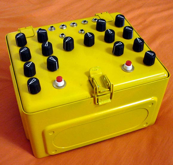
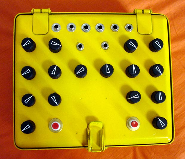
finally i got it in a decent case...
so here are some pic´s of my Dual DS7 clones - -
just need to ad labels to knobs
sound samples are soon here also
daniel
| Description: |
|
| Filesize: |
45.05 KB |
| Viewed: |
88793 Time(s) |
|
| Description: |
|
| Filesize: |
49.7 KB |
| Viewed: |
88793 Time(s) |
|
|
|
|
Back to top
|
|
|
dnny
Joined: Mar 12, 2005
Posts: 519
Location: Helsinki, Finland
Audio files: 8
|
|
|
Back to top
|
|
|
mosc
Site Admin
Joined: Jan 31, 2003
Posts: 18328
Location: Durham, NC
Audio files: 235
G2 patch files: 60
|
| Posted: Thu Jun 16, 2005 11:23 am Post subject:
|
|
|
Daniel, looks and sounds great. Congratulations. I'm sure you'll have many hours of fun playing with these toys.
If you want a good program for recording stuff on your PC that is free, be sure to check out Audacity. Please keep us posted with more mp3s and pictures. 
_________________
--Howard
my music and other stuff |
|
|
Back to top
|
|
|
dnny
Joined: Mar 12, 2005
Posts: 519
Location: Helsinki, Finland
Audio files: 8
|
| Posted: Tue Jun 28, 2005 4:00 am Post subject:
DS7 mods |
|
|
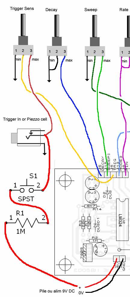
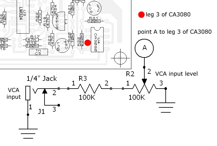
so here are some pics of DS7 mods
first there is the VCA input mod. (for signal not for CV)
run wire from jack to leg 3 of CA3080 via 100K resistor and 100K pot.
to the panel you ad VCA input (jack) and VCA input level (pot)
and second comes the manual trigger mod:
run wire from +9V via 1M resistor to momentary push button and from there to trigger sens pot point 3.
to the panel you ad momentary push button.
(you get continuos signal if you hold the button down.)
daniel
ps. the RJWsofts Schematic Publisher is great and the pics are made whit it.
Schematic Publisher free download
| Description: |
|
| Filesize: |
38.46 KB |
| Viewed: |
88720 Time(s) |
|
| Description: |
|
| Filesize: |
38.01 KB |
| Viewed: |
88720 Time(s) |
|
Last edited by dnny on Fri Nov 25, 2005 4:38 am; edited 2 times in total |
|
|
Back to top
|
|
|
Wild Zebra

Joined: Apr 28, 2005
Posts: 806
Location: Ohio
Audio files: 5
|
| Posted: Tue Jun 28, 2005 7:26 am Post subject:
|
|
|
Cool thanks dnny. Can't wait to dig into those ds7's
_________________
"your stripes are killer bro" |
|
|
Back to top
|
|
|
discointellect

Joined: Jan 08, 2006
Posts: 8
Location: UK
|
| Posted: Sun Jan 08, 2006 12:42 am Post subject:
|
|
|
I was looking at building a couple of the DS-7s but I can't find the CA3080 anywhere (I think it's been discontinued) - anyone know where I might be able to source one (in the UK) or of an equivalent chip that could be used?
Thanks. |
|
|
Back to top
|
|
|
Macaba
Joined: Jul 13, 2005
Posts: 160
Location: UK
|
| Posted: Sun Jan 08, 2006 4:04 am Post subject:
|
|
|
| The chip that everyone knows about is the LM13700, which does the same thing, EXCEPT that its in a package twice as big, because it has two transconductance amplifiers on the same chip (twice the value!). So there is a replacement, but its rather impratical to get it on the board. Upon reading the datasheet, I notice at the top it says that there is NO recommended replacement. Outta luck? |
|
|
Back to top
|
|
|
discointellect
Joined: Jan 08, 2006
Posts: 8
Location: UK
|
| Posted: Sun Jan 08, 2006 5:04 am Post subject:
|
|
|
Ta, bit of a pain that it won't fit the PCB but I'm planning on building a pair of them so I expect I can hack something together (flying leads to a bit of stripboard or something equally professional looking). I'm a complete novice at this electronics lark, so today I learn the no doubt valuable lesson of "make sure all the necessary components are available before you order the PCB"  |
|
|
Back to top
|
|
|
dnny
Joined: Mar 12, 2005
Posts: 519
Location: Helsinki, Finland
Audio files: 8
|
| Posted: Sun Jan 08, 2006 7:06 am Post subject:
|
|
|
| Macaba wrote: | | The chip that everyone knows about is the LM13700, which does the same thing, EXCEPT that its in a package twice as big, because it has two transconductance amplifiers on the same chip (twice the value!). So there is a replacement, but its rather impratical to get it on the board. Upon reading the datasheet, I notice at the top it says that there is NO recommended replacement. Outta luck? |
you can use the "dead bug" mounting method:

or you can use the layout i kloned it has a extra space to fit the LM13700 at the bottom.
see pic.

and it holds three DS7´s on one 10cmx16cm board.
and if you build all three DS7´s. you need 2 LM13700 so the one half(of LM13700) unused can be used on Ring Modulator - See: Aaron Crams ringmodulator
and if you dont find the LM13700 (dual Operational Transconductance Amp)
try thease substitutes
LM13600
NE5517
AU5517
NTE870
daniel |
|
|
Back to top
|
|
|
discointellect
Joined: Jan 08, 2006
Posts: 8
Location: UK
|
| Posted: Wed Jan 18, 2006 12:21 pm Post subject:
|
|
|
| Cheers for the help - got my first one up and running with the LM13700; I've got a second DS7 PCB so I'll wire that in to the other half. Really cool little device and nice and simple to put together - I'm planning on getting a pair of DS8 boards as well and casing the whole lot up to act as a 4 channel percussion synth to be sequenced by my Regelwerk. Should be fun |
|
|
Back to top
|
|
|
dnny
Joined: Mar 12, 2005
Posts: 519
Location: Helsinki, Finland
Audio files: 8
|
| Posted: Sun Apr 09, 2006 2:25 am Post subject:
|
|
|
since the CA3080 (2MHz, Operational Transconductance Amplifier) is coming more hard to find. i made some adjustments to the PCB so you can use one LM13700 or LM17600 and have two DS7 run whit that one chip.
here it comes :

and here is the layout whit tree jumper wires:

when you want a hi-resolution image of the PCB just email me and i will be glad to post it to you
HTH
daniel
_________________
Association of experimental electronics
www.koelse.org
flickr: cable porn group |
|
|
Back to top
|
|
|
Pehr

Joined: Aug 14, 2005
Posts: 1307
Location: Björkvik, Sweden
Audio files: 2
|
|
|
Back to top
|
|
|
dnny
Joined: Mar 12, 2005
Posts: 519
Location: Helsinki, Finland
Audio files: 8
|
| Posted: Wed Apr 26, 2006 10:37 pm Post subject:
|
|
|
nice.
thanks Pehr for this tip.
i just got twenty LM13600´s from ELFA, so i think i will be fine whit those for a while. but for others this is great news.
_________________
Association of experimental electronics
www.koelse.org
flickr: cable porn group |
|
|
Back to top
|
|
|
Pehr
Joined: Aug 14, 2005
Posts: 1307
Location: Björkvik, Sweden
Audio files: 2
|
|
|
Back to top
|
|
|
Wild Zebra
Joined: Apr 28, 2005
Posts: 806
Location: Ohio
Audio files: 5
|
| Posted: Mon May 08, 2006 7:44 am Post subject:
|
|
|
Thanks dnny,
Although I have seen CA3080, It's nice to see a new design and using only one chip. Who doensn't need a couple of extra LM13700's laying around, Guess it's time I order up. I still need to make those DS7's.
You sent those files many moons ago.
_________________
"your stripes are killer bro" |
|
|
Back to top
|
|
|
creekree

Joined: Mar 30, 2006
Posts: 192
Location: Morgenland Neukölln
Audio files: 1
|
Posted: Mon May 29, 2006 12:33 pm Post subject:
 |
|
|
hi all,
been lurking here for quite some time now, and if i am not mistaken, this is my first post, so hello!
dnny kindly sent me the pcb layout for the ds7-clone, which i now have finished. alas... it is not working. actually, i made some kind of kraakdoos, since i do get strange noises by putting my finger on various spots of the pcb. however, i´d like to trigger it with my 606. maybe with the 707. whatever - i want it to work the way it is intended to work.
my question: i didnt have two specific components at hand, so i substituted C6, a .1uF electrolytic, with a .1uF tantalum cap.
also i used a ceramic 1n cap for C5.
could this be the problem?
i do not know that much about caps to answer those questions myself, so maybe someone here could enlighten me?
oh, the voltages on the ICs are correct, and the pcb i made looks quite good too - so i´d like to exclude the possibility of shortcuts.
thank you, creekree |
|
|
Back to top
|
|
|
toppobrillo

Joined: Dec 10, 2005
Posts: 766
Location: oakland, ca
G2 patch files: 1
|
| Posted: Mon May 29, 2006 1:05 pm Post subject:
|
|
|
hey creekree, welcome to the forum...
so first off, C6 in the schematic is actually a 1uF... it's just a decoupling cap [eliminating a DC bias] and .1 would work here too, but like this, the cap is a high pass filter and you would get less low frequency signal at the output. if you use a polarized cap, make sure it is oriented properly.
ok, and C5 in the schematic is actually supposed to be 100nF [.1 uF], i suspect this to be your problem, as a smaller cap in this position like 1nF [.001uf] would make very high frequency oscillations with very small amplitude.
replace this cap with a .1uF ceramic, mylar, whatever.. if you use a polarized, make sure it is negative end to ground.
anyways, good luck, hope this is the fix..
josh |
|
|
Back to top
|
|
|
creekree
Joined: Mar 30, 2006
Posts: 192
Location: Morgenland Neukölln
Audio files: 1
|
| Posted: Tue May 30, 2006 7:38 am Post subject:
|
|
|
topp,
youre the man!
your suggestions about the capacitor values were right - i didnt notice since i just collected the parts according to the BOM and then stuffed the PCB.
the BOM is not correct on those caps.
also, and that was the tricky part, the BC550 i used was broken. i guess that is the price you have to pay when you salvage parts from broken electronic devices - they´re not broken for no reason, eh?
anyway, thanks for the help. my ds7 is working just fine now! - time to look into adding a noise source.
creekree |
|
|
Back to top
|
|
|
toppobrillo
Joined: Dec 10, 2005
Posts: 766
Location: oakland, ca
G2 patch files: 1
|
| Posted: Tue May 30, 2006 8:17 am Post subject:
|
|
|
 cool glad it works! cool glad it works! |
|
|
Back to top
|
|
|
dnny
Joined: Mar 12, 2005
Posts: 519
Location: Helsinki, Finland
Audio files: 8
|
| Posted: Tue May 30, 2006 1:01 pm Post subject:
|
|
|
 creekree - creekree -
glad to hear that it works - now:)
and doesn't it sound great for such a small and easy to build device?
i think everyone should make at least one of these.
_________________
Association of experimental electronics
www.koelse.org
flickr: cable porn group |
|
|
Back to top
|
|
|
creekree
Joined: Mar 30, 2006
Posts: 192
Location: Morgenland Neukölln
Audio files: 1
|
| Posted: Tue May 30, 2006 2:30 pm Post subject:
|
|
|
yeah dnny youre right - nice toy indeed, it does go very well with my modded 606.
it is easy to build, i spent one lazy rainy day on etching, stuffing the pcb and building a case - all in all maybe 3 hours? if it hadnt been for my problems, that is... (dang 550, who would´ve thought...)
i added a switch to toggle between 100 and 560 on R11 as the "bass boost" sometimes goes undesirably too low (speak: speaker-blowing) for my taste.
how does the VCA input behave? is it just an audio gate or does it filter the signal? havnt tried it yet but will someday (i have plenty of jacks lying around - people! salvage junk! harvest parts! save money!)
thanks to monsieur bareille for cloning the thing and publishing schematics!
... also thanks to you, dnny, for the directions of how to add a trigger button.
as a sidenote: my girlfriend immediately fell in love with the ds7. she is a huge kraakdoos (cracklebox) fan (probably one of the best gift EVER that i gave her) and we would jam for like one hour with the 606, x0xb0x and her tweaking the hell out of the ds7 running through a delay. now she wants the noise source implemented - "hey, can you put more knobs on this thing that i can turn?!?" oddly enough, she does not want to learn to operate the x0x... sigh, girls......
Last edited by creekree on Tue May 30, 2006 6:38 pm; edited 1 time in total |
|
|
Back to top
|
|
|
Uncle Krunkus
Moderator

Joined: Jul 11, 2005
Posts: 4761
Location: Sydney, Australia
Audio files: 52
G2 patch files: 1
|
| Posted: Tue May 30, 2006 2:47 pm Post subject:
|
|
|
Hey Creekree,
be thankful your girlfriend is interested in electronic music at all!! 
I'm thinking I might have a go at one of these DS7s myself!!
_________________
What makes a space ours, is what we put there, and what we do there. |
|
|
Back to top
|
|
|
dnny
Joined: Mar 12, 2005
Posts: 519
Location: Helsinki, Finland
Audio files: 8
|
| Posted: Tue May 30, 2006 10:18 pm Post subject:
|
|
|
| Uncle Krunkus wrote: | | I'm thinking I might have a go at one of these DS7s myself!! |
on stripboard maybe ? that would be so cool. I'm a fan of your boards.
talking about girlfriends - after i build the DS7 my girl wanted to build the noise source for it - and she did a great job. now she wants to build the DS7 ... soon we need two soldering stations ...
here is a blurry pic of Ray's Multi Noise and Random Gate/Trigger Generator

_________________
Association of experimental electronics
www.koelse.org
flickr: cable porn group |
|
|
Back to top
|
|
|
|

 Forum index » DIY Hardware and Software

