| Author |
Message |
Monstruarte

Joined: Sep 25, 2009
Posts: 73
Location: Argentina
|
 Posted: Sun Nov 01, 2009 12:34 pm Post subject:
Atari punk console + Baby sequencer 4017 IC Posted: Sun Nov 01, 2009 12:34 pm Post subject:
Atari punk console + Baby sequencer 4017 IC |
  |
|
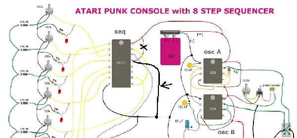
hello all, I'm doing this atari Sequencer and I think there's an error in the drawing can not see. the atari is working but when I press the switch to ring the Sequencer, the sound disappears. please help ....

http://www.owyheesound.com/sequencer.php |
|
|
Back to top
|
|
 |
electri-fire
Joined: Jul 26, 2006
Posts: 536
Location: Dordrecht NL
Audio files: 4
G2 patch files: 4
|
|
|
Back to top
|
|
|
Mubo
Joined: Jul 21, 2008
Posts: 16
Location: ft.lauderdale
|
| Posted: Tue Nov 10, 2009 11:41 am Post subject:
|
|
|
hey guys... which schematic is correct? ... they both have the same corrections... are they both correct?
Thanks |
|
|
Back to top
|
|
|
electri-fire
Joined: Jul 26, 2006
Posts: 536
Location: Dordrecht NL
Audio files: 4
G2 patch files: 4
|
| Posted: Tue Nov 10, 2009 12:35 pm Post subject:
|
|
|
Now they're both correct indeed. I think, I didn't build this circuit. My correction was based on my experience with the 4017 and the 4017 datasheet.
Monstruarte must have changed the attachment. Yes that's it. Hey, if you look closely we're even credited for the correction.
Monstruarte, you might inform the reader of your edit to avoid confusion.
. |
|
|
Back to top
|
|
|
Monstruarte
Joined: Sep 25, 2009
Posts: 73
Location: Argentina
|
| Posted: Tue Nov 17, 2009 7:33 am Post subject:
|
|
|
sorry, my mistake was to directly copy the url of the image, so the image was updated and changed without my noticing, I'll upload the old pictures that I had before the circuit was updated, only to discuss on the subject. source page is this: http://owyheesound.com/sequencer.php
I opened another Argentina post on a page (this in Spanish), http://www.psicofxp.com/forums/electronica.149/973268-leds-en-lugar-indicado-secuenciador-sonido.html
there user "tolemaic" raises a good system of LEDs using transistors, anyway. the interesting thing is that in regard to replacing the switch, the DPDT, this less versatile than the last, because if you choose to sequence the first 555, the second is controlled by LDR (photoresistor), this would not be able to sequence and control the first 555 at the same time. The switches are better in the first version of the circuit.
version1

Version2

Version3
 |
|
|
Back to top
|
|
|
Monstruarte
Joined: Sep 25, 2009
Posts: 73
Location: Argentina
|
| Posted: Tue Nov 17, 2009 2:06 pm Post subject:
|
|
|
| WTF??? 6-volt battery?? I think it is wrong, or not? |
|
|
Back to top
|
|
|
-minus-
Joined: Oct 26, 2008
Posts: 787
Audio files: 13
|
| Posted: Thu Jan 07, 2010 5:40 am Post subject:
|
|
|
I'm suggesting it MUST be a 9v battery...
I've drawn up a stripboard version of this (version 3). Going to build it in the next couple of days. I'm thinking I might breadboard it first though! Just wondering if anyone here has built it yet?
Thanks.. |
|
|
Back to top
|
|
|
LektroiD

Joined: Aug 23, 2008
Posts: 1019
Location: Scottish Borders
Audio files: 2
G2 patch files: 2
|
| Posted: Thu Jan 07, 2010 5:54 pm Post subject:
|
|
|
| -minus- wrote: | I'm suggesting it MUST be a 9v battery...
I've drawn up a stripboard version of this (version 3). Going to build it in the next couple of days. I'm thinking I might breadboard it first though! Just wondering if anyone here has built it yet?
Thanks.. |
I'd like to see your layout. I'm not fantastic at stripboard layouts myself, or I'd have built it already.
_________________
LektroiD |
|
|
Back to top
|
|
|
-minus-
Joined: Oct 26, 2008
Posts: 787
Audio files: 13
|
| Posted: Fri Jan 08, 2010 3:47 am Post subject:
|
|
|
Hello again LectroiD! Fancy meeting you here!
Yes, I shall post the stripboard drawing. At present it is a pencil on paper job. I am just about to make up the board tonight. If it works, I shall do up an illustration in Illustrator and share.
I'm probably not the best stripboarder myself. It's about getting it into a small footprint I think, which I probably haven't achieved just yet with this 26X18 hole version.
Stay tuned though... will post diagram in the next few days. |
|
|
Back to top
|
|
|
-minus-
Joined: Oct 26, 2008
Posts: 787
Audio files: 13
|
| Posted: Mon Jan 11, 2010 10:08 am Post subject:
|
|
|
ok... Update on the stripboard.
Got the thing made up... but no go as yet. Need to go over my stripboard sketch and see if I went wrong somewhere. Will keep at it for a bit, but just wondering if anyone has had any luck with this in any fashion? I'm using the oscillator switch set up from version 1 posted above, working off the diagram from version 3.
Post investigation results as soon as I can! Soon as it works I'll draw up the confirmed stripboard and post here... |
|
|
Back to top
|
|
|
-minus-
Joined: Oct 26, 2008
Posts: 787
Audio files: 13
|
| Posted: Mon Jan 11, 2010 10:57 am Post subject:
|
|
|
Getting significant heating of the 555 clock IC....
It's 5AM here and I need some shut eye! Will get back to this tomorrow. I have a circuit i made up a few months back which is a 555 and 4017 set up. It appears to have different components in different places in relation to the 555 used for the clock. Might try hooking this up to a breadboard of the oscillator A & B part of this. First I'll go over what I have made up tonight.... |
|
|
Back to top
|
|
|
airfrankenstein
Joined: Jan 10, 2010
Posts: 62
Location: france
|
| Posted: Mon Jan 11, 2010 12:31 pm Post subject:
Atari punk console + Baby sequencer 4017 IC |
|
|
| On my second attempt....the sequencer is running, the last led doesn't light for some reason. I can adjust the rate, but I've got a bad solder connection at the audio out so no sound. I burned off the soldering pad at that spot and have no idea how to repair that. If I work that out I'll let you know if it works. |
|
|
Back to top
|
|
|
fonik

Joined: Jun 07, 2006
Posts: 3950
Location: Germany
Audio files: 23
|
| Posted: Mon Jan 11, 2010 4:08 pm Post subject:
Re: Atari punk console + Baby sequencer 4017 IC |
|
|
| airfrankenstein wrote: | | I burned off the soldering pad at that spot and have no idea how to repair that. If I work that out I'll let you know if it works. |
carefully remove the soldermask from the trace that led to the now non-existent pad. carefully. then solder directly to the now exposed copper trace...
_________________

cheers,
matthias
____________
Big Boss at fonitronik
Tech Buddy at Random*Source |
|
|
Back to top
|
|
|
-minus-
Joined: Oct 26, 2008
Posts: 787
Audio files: 13
|
| Posted: Mon Jan 11, 2010 6:43 pm Post subject:
|
|
|
I was just looking over the APC part of this design.... I built a stand alone APC a while back using the 2X 555 stripboard layout posted here:
http://electro-music.com/forum/topic-12644-50.html
It's the one posted by PARA (Wed Oct 17, 2007 6:24 am). The only thing wrong with it was the gap in the rail between the two IC's... this should be a join.
On this baby 10 version we have here, there is a cap between pin 1 & 2 of OSC A. It is not the case on the stand alone APC. Wondering why?
What I'm thinking is that I am going to play around with a breadboard for a day and see if I can try get the stand alone APC and my decade counter stripboard I made some time ago, linked together. I should probably be troubleshooting this board though... I'm still a learner as you can tell! I'm becoming increasingly aware that breadboarding designs first is a worthwhile activity! Breadboards- the staff of life! |
|
|
Back to top
|
|
|
-minus-
Joined: Oct 26, 2008
Posts: 787
Audio files: 13
|
| Posted: Mon Jan 11, 2010 6:48 pm Post subject:
|
|
|
Sorry, just realized there is a cap between pin 1 & 2! It just runs around a different route! Happy breadboarding!  |
|
|
Back to top
|
|
|
airfrankenstein
Joined: Jan 10, 2010
Posts: 62
Location: france
|
| Posted: Mon Jan 11, 2010 11:25 pm Post subject:
Re: Atari punk console + Baby sequencer 4017 IC |
|
|
| fonik wrote: | | airfrankenstein wrote: | | I burned off the soldering pad at that spot and have no idea how to repair that. If I work that out I'll let you know if it works. |
carefully remove the soldermask from the trace that led to the now non-existent pad. carefully. then solder directly to the now exposed copper trace... |
Will that work with perfboard ? |
|
|
Back to top
|
|
|
airfrankenstein
Joined: Jan 10, 2010
Posts: 62
Location: france
|
| Posted: Mon Jan 11, 2010 11:34 pm Post subject:
|
|
|
| -minus- wrote: | I was just looking over the APC part of this design.... I built a stand alone APC a while back using the 2X 555 stripboard layout posted here:
http://electro-music.com/forum/topic-12644-50.html
It's the one posted by PARA (Wed Oct 17, 2007 6:24 am). The only thing wrong with it was the gap in the rail between the two IC's... this should be a join.
On this baby 10 version we have here, there is a cap between pin 1 & 2 of OSC A. It is not the case on the stand alone APC. Wondering why?
What I'm thinking is that I am going to play around with a breadboard for a day and see if I can try get the stand alone APC and my decade counter stripboard I made some time ago, linked together. I should probably be troubleshooting this board though... I'm still a learner as you can tell! I'm becoming increasingly aware that breadboarding designs first is a worthwhile activity! Breadboards- the staff of life! |
Getting some sound now.
I've managed so far to get one working but never both at the same time in a convincing manner. I must have another short circuit somewhere cos all I'm getting is a whining sound and a 80 bpm sequencer pattern.
Also, the 1M pot cuts the sequencing well before the top of the dial, whether I've got sound or not. |
|
|
Back to top
|
|
|
-minus-
Joined: Oct 26, 2008
Posts: 787
Audio files: 13
|
| Posted: Tue Jan 12, 2010 5:22 am Post subject:
|
|
|
| Good to see you have some sound airfrankenstein! I pulled out the 4017 and clock 555 IC's from their sockets and have the APC part running fine, so my problem is not there. I'm thinking in the final build I wont bother with the LDR's. I'm going to track down what is wrong with my clock and decade counter section of my stripboard. Post results soon.... |
|
|
Back to top
|
|
|
-minus-
Joined: Oct 26, 2008
Posts: 787
Audio files: 13
|
| Posted: Tue Jan 12, 2010 7:44 am Post subject:
|
|
|
Clearly my problem is in the 4017 and 555 clock section. No LED's... nothing! Not quite sure what to do about this. Bit out of my depth here. I cut out all the crappy LDR's... Might start breadboarding this now. Perhaps there is a problem with the stripboard I made? Something I cant see... Anyone else had luck? More importantly- any CONFIRMED builds?  |
|
|
Back to top
|
|
|
-minus-
Joined: Oct 26, 2008
Posts: 787
Audio files: 13
|
| Posted: Tue Jan 12, 2010 8:44 am Post subject:
|
|
|
| airfrankenstein wrote: | | -minus- wrote: | I was just looking over the APC part of this design.... I built a stand alone APC a while back using the 2X 555 stripboard layout posted here:
http://electro-music.com/forum/topic-12644-50.html
It's the one posted by PARA (Wed Oct 17, 2007 6:24 am). The only thing wrong with it was the gap in the rail between the two IC's... this should be a join.
On this baby 10 version we have here, there is a cap between pin 1 & 2 of OSC A. It is not the case on the stand alone APC. Wondering why?
What I'm thinking is that I am going to play around with a breadboard for a day and see if I can try get the stand alone APC and my decade counter stripboard I made some time ago, linked together. I should probably be troubleshooting this board though... I'm still a learner as you can tell! I'm becoming increasingly aware that breadboarding designs first is a worthwhile activity! Breadboards- the staff of life! |
Getting some sound now.
I've managed so far to get one working but never both at the same time in a convincing manner. I must have another short circuit somewhere cos all I'm getting is a whining sound and a 80 bpm sequencer pattern.
Also, the 1M pot cuts the sequencing well before the top of the dial, whether I've got sound or not. |
AIRFRANKENSTEIN: I've just breadboarded the sequencer section of the circuit and it works. I too was having the 1M pot problem of it cutting out. Inserting a 1K resistor along the wire from pin 8 of the clock 555 and the 1M pot has stopped this happening. Hope this helps!  |
|
|
Back to top
|
|
|
airfrankenstein
Joined: Jan 10, 2010
Posts: 62
Location: france
|
| Posted: Tue Jan 12, 2010 1:50 pm Post subject:
Atari punk console + Baby sequencer 4017 IC |
|
|
Minus,
Thanks for the tip about the rate control.
Are you able to get a good fast rate?
I mailed Nathan at owyheesound for some help. I believe he's the one who posted the layout originally even though it's not necessarily his design.
" The 1meg pot cuts out because it is a pot that is easy to get and does not cost much. You could add a resister in series with the pot to prevent the cut out (a value between 200K and 500K is where I would start), or you might even try changing the value of the cap. A slightly higher value and then a slightly lower value (slight might mean by half or less of the existing cap's value)."
and the following for putting an output jack which would allow to plug into other devices (I have a lot of pedals for ex)...
"Regarding the output jack, the green wire that goes across the bottom of the drawing is the one you tap off of and connect to the hot pin of your jack and then connect the ground of the battery terminal to the ground of the jack. This may or may not have enough power to do what you want. Because some of the electricity is going to the 555 chip to control the oscillator there may not be enough left over power to run your other device. you could disconnect the line going to the OSC or you could send the signal to a buffer and drive as many devices as you like. A good buffer chip to use is a 4050."
also just discovered the baby five atari fuzz which is a nice take on the sequencer apc combo in this post. just google and check out the clips.
cheers |
|
|
Back to top
|
|
|
airfrankenstein
Joined: Jan 10, 2010
Posts: 62
Location: france
|
Posted: Tue Jan 12, 2010 4:10 pm Post subject:
Subject description: connecting apc and sequencer |
|
|
ok so I mounted an apc using a 556 and I've got the sequencer clicking and the leds flashing. I read somewhere that the output of the sequencer had to go to pin 2 on the 556 (threshhold). tried that but nothing changes.
Any ideas as to what might be wrong ?
Thanks again |
|
|
Back to top
|
|
|
airfrankenstein
Joined: Jan 10, 2010
Posts: 62
Location: france
|
Posted: Tue Jan 12, 2010 5:57 pm Post subject:
Subject description: working !!! |
|
|
finally got it to work.
if you're using a 556 apc the sequencer goes to pin 6.
now to get a preamp and a fuzz in there. |
|
|
Back to top
|
|
|
-minus-
Joined: Oct 26, 2008
Posts: 787
Audio files: 13
|
| Posted: Wed Jan 13, 2010 4:14 am Post subject:
|
|
|
Good to see it's working airfrankenstein! I seem to get a reasonable rate with the 1K resistor to the 1M pot. It was the first resistor I picked up on my table. Perhaps a 500 ohm would increase the rate?
I was wondering which switching diagram you built from? I tried version 1. I'm thinking I might see what version 3 does.
Also, how did you build this? Etch a board? Vero/stripboard? just wondering....
ALSO: What about the 100K pots? Are you finding that the wiring of these is correct?
I got a breadboard of this 4017 and dual 555 APC going last night. I need to sort out what happens with the APC pots though. I seem to only get a circuit bent variation working... but I wont mention that as it will only confuse the issue!  |
|
|
Back to top
|
|
|
-minus-
Joined: Oct 26, 2008
Posts: 787
Audio files: 13
|
| Posted: Wed Jan 13, 2010 6:00 am Post subject:
|
|
|
FINALLY! Got this working! My stripboard diagram was correct after all! I was taking the (-) from the CLOCK to the 100K pots from the wrong side of the 1uF capacitor... essentially from the (+) side which is pin 2, not the (-) side which is pin 1! Also, I used the DPDT switch method as shown on version 3. The only problem I have is the LED's on each step. They don't light up... or if they do, it's ever so slight. Might have to change this around a bit... change the resistor value or the location of them.
I am just about to start up Illustrator and do up a diagram of this stripboard for all to see. Never added an attachment to a post before, so please bare with me! Might take a few hours.... 
Last edited by -minus- on Fri Jan 15, 2010 5:50 am; edited 2 times in total |
|
|
Back to top
|
|
|
|

 Forum index » DIY Hardware and Software