| Author |
Message |
Tronato
Joined: Sep 21, 2007
Posts: 274
Location: Florida
Audio files: 2
|
 Posted: Thu Oct 04, 2007 2:04 pm Post subject: Posted: Thu Oct 04, 2007 2:04 pm Post subject:
|
  |
|
Hello Blue Hell:
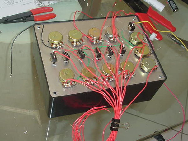
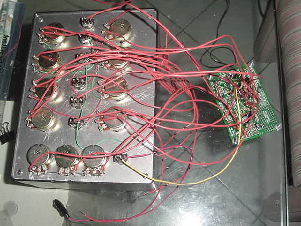
Since the cables that connect the Front Panel to the Printed Circuit Board are the closest I have seen to an octopus I would like to try to avoid soldering/unsoldering once the cables are connected again.
Since the I.C. has a socket, would carefully bending pin 12 so that it remains out of the socket have the same effect? After testing I would carefully bend it again into place. This for Voice B. For Voice A it would be pin 2... would these unconnected pins ruin the I.C. when power is applied?
Sounds crazy?
Thanks!
TRO |
|
|
Back to top
|
|
 |
blue hell
Site Admin

Joined: Apr 03, 2004
Posts: 24655
Location: The Netherlands, Enschede
Audio files: 326
G2 patch files: 320
|
| Posted: Thu Oct 04, 2007 4:32 pm Post subject:
|
|
|
It's OK to bend out pin 12, when you set "Zaniness amount" to zero and "Wackiness" and "Wackyness too" both off ... shit where is WSWB going ... and DPSB, damn, those can carry signals as well, now I see why it's called what it is, this WSG  Erm, it looks most like those are just labels not connected to anything .. so, yes, then it would probably be silent, bit I can't find quickly what those labels mean. Erm, it looks most like those are just labels not connected to anything .. so, yes, then it would probably be silent, bit I can't find quickly what those labels mean.
Cut out that resistor ! that works for sure 
_________________
Jan
also .. could someone please turn down the thermostat a bit.
 |
|
|
Back to top
|
|
|
blue hell
Site Admin
Joined: Apr 03, 2004
Posts: 24655
Location: The Netherlands, Enschede
Audio files: 326
G2 patch files: 320
|
| Posted: Thu Oct 04, 2007 4:34 pm Post subject:
|
|
|
| Tronato wrote: | Sounds crazy?
|
No not at all, it can be very useful to do things like that.
_________________
Jan
also .. could someone please turn down the thermostat a bit.
|
|
|
Back to top
|
|
|
Tronato
Joined: Sep 21, 2007
Posts: 274
Location: Florida
Audio files: 2
|
| Posted: Thu Oct 04, 2007 4:41 pm Post subject:
|
|
|
Hello again!
Those letters correspond to the cables that are coming from the Front Panel, a drawing of which is on the same page as the circuit if you're looking at Ray's WSG Web Page...
But I just found the most amazingly simple solution... it's so obvious that if it would've been a snake it would've bitten me!
I'll remove both resistors and attach them underneath the board... (LOL)...
that way the cables won't bother me!
What do you think?
TRO |
|
|
Back to top
|
|
|
blue hell
Site Admin
Joined: Apr 03, 2004
Posts: 24655
Location: The Netherlands, Enschede
Audio files: 326
G2 patch files: 320
|
| Posted: Thu Oct 04, 2007 4:47 pm Post subject:
|
|
|
| Tronato wrote: | | What do you think? |
You've seen the light man 
Seriously, that's a very good idea, experiment, that's the fun part of things not working.
_________________
Jan
also .. could someone please turn down the thermostat a bit.
|
|
|
Back to top
|
|
|
Pehr

Joined: Aug 14, 2005
Posts: 1307
Location: Björkvik, Sweden
Audio files: 2
|
| Posted: Fri Oct 05, 2007 2:08 am Post subject:
|
|
|
| Tronato wrote: | | How would you start from the output backwards? I can't see how the filter would make the noise without having any input, but then the name of the on/off switch says it all: anything is possible in the Twilight Zone! (LOL) |
I would start with checking the value of C6, is it right? is it soldered with the right polarity?
Then check the values of R12, R4, C2, C3, R3, R31, R32 (is the resonance turned all the way down), R35, R8, R17, R16, C8, and also check if they´re connected properly.
Measure the voltage over C8, it should be 4.5V
And then continue checking component values towards the voices, C1, R10, R2, R5...
EDIT: Perhaps the transistors isn't connected properly. I've had that problem once with an SL. Try to warm up the solder and push them down a little more.
_________________
YouTube channel
flickr photostream
http://loxodrom.blogspot.com
http://www.garageband.com/artist/loxodrom
http://soundcloud.com/loxodrom
Last edited by Pehr on Fri Oct 05, 2007 4:08 am; edited 1 time in total |
|
|
Back to top
|
|
|
Tronato
Joined: Sep 21, 2007
Posts: 274
Location: Florida
Audio files: 2
|
| Posted: Fri Oct 05, 2007 3:06 am Post subject:
|
|
|
Hello Pehr:
I assume that this should be done with the complete Front Panel (that is pots and switches) connected to the PCB, right?
Since they are currently disconnected my idea was to connect for example the 3 pots and the switch associated with the filter and then check with the signal tracer in the filter section if the annoying noise was present. If it wasn't the perform the same procedure with voice 1 and then with voice 2...
With what you are suggesting, how can I know what voltage should be present where?
Thanks
TRO |
|
|
Back to top
|
|
|
Pehr
Joined: Aug 14, 2005
Posts: 1307
Location: Björkvik, Sweden
Audio files: 2
|
| Posted: Fri Oct 05, 2007 4:05 am Post subject:
|
|
|
| Tronato wrote: | I assume that this should be done with the complete Front Panel (that is pots and switches) connected to the PCB, right?
|
Not neccesary, you could do fine with the pots and switches in the filter.
| Tronato wrote: | Since they are currently disconnected my idea was to connect for example the 3 pots and the switch associated with the filter and then check with the signal tracer in the filter section if the annoying noise was present. If it wasn't the perform the same procedure with voice 1 and then with voice 2...
|
That sounds good.
| Tronato wrote: |
With what you are suggesting, how can I know what voltage should be present where? |
You mean the voltage over C8? Measure with a multimeter set to DC, one probe to ground (black) and the other (red) to the point you want measure.
Since the 9V is divided over two 100k resistors it should be 9V/2=4.5V present there.
_________________
YouTube channel
flickr photostream
http://loxodrom.blogspot.com
http://www.garageband.com/artist/loxodrom
http://soundcloud.com/loxodrom |
|
|
Back to top
|
|
|
Tronato
Joined: Sep 21, 2007
Posts: 274
Location: Florida
Audio files: 2
|
| Posted: Fri Oct 05, 2007 4:47 am Post subject:
|
|
|
Hello again:
No I don't mean across C8, I mean across other points in the circuit...
Thanks!
TRO |
|
|
Back to top
|
|
|
Pehr
Joined: Aug 14, 2005
Posts: 1307
Location: Björkvik, Sweden
Audio files: 2
|
|
|
Back to top
|
|
|
Scott Stites
Janitor


Joined: Dec 23, 2005
Posts: 4127
Location: Mount Hope, KS USA
Audio files: 96
|
| Posted: Fri Oct 05, 2007 1:01 pm Post subject:
|
|
|
I'm curious:
What type of jacks are you using? 1/4", 3.5 mm, banana?
What type of cable are you using to connect to the amplifier (coaxial grounded, etc.)?
I just get the feeling reading through this that it is 60 cycle hum, regardless of whether it's battery powered or not. Connecting the AC/DC supply then touching the controls and hearing a difference is a real good clue right there.
If the jacks do not have a common ground with the amplifier, you're likely to get that. If it's a bare aluminum panel they're going to connect together through the panel, depending on the type of jack. If they don't have the ground they need, and it is not common to the amplifier, your panel could well act as a LF receiver tuned to our favorite station, 60 Hz Golden Oldies. If that's the case, I'd be really suprised you haven't received Wall of Voodoo as well (Mexican Radio). Maybe it's not in the bounce path over in Florida.....
Cheers,
Scott
_________________
My Site |
|
|
Back to top
|
|
|
Tronato
Joined: Sep 21, 2007
Posts: 274
Location: Florida
Audio files: 2
|
| Posted: Fri Oct 05, 2007 5:56 pm Post subject:
|
|
|
Hello Scott:
I was wondering if you were ever going to read this post!
Once I get my WSG working I'll get into your Vactrol mods.
Now to business...
1.- I bought Ray's kit. It uses a 1/4 " jack.
2.- I connect to my amp with a standard guitar plug (1/4" plugs on both ends) coaxial cable which I use with my Electribe AE-1 with no problem whatsoever.
3.- There is a seamless continuity between the pots, switches, aluminum panel, PCB's ground and the audio jack's ring (signal on tip).
Thus said I'll invert the jack connection and see what happens.
Thanks!
TRO |
|
|
Back to top
|
|
|
Scott Stites
Janitor
Joined: Dec 23, 2005
Posts: 4127
Location: Mount Hope, KS USA
Audio files: 96
|
| Posted: Sun Oct 07, 2007 7:31 am Post subject:
|
|
|
Hey Tronato,
Well, it was a shot in the dark. You can figure out pretty quickly if the jacks have the ground wired on the right lug if you have a spare jack. Just to double-check, you can plug a cable into this spare jack and check continuity of the ground of the cable to the ground lug on the jack and tip of the cable to the tip lug of the jack.
The positions of those lugs change from manufacturer to manufacturer, so it can happen.
Take care,
Scott
_________________
My Site |
|
|
Back to top
|
|
|
RF

Joined: Mar 23, 2007
Posts: 1502
Location: Northern Minnesota, USA
Audio files: 28
|
| Posted: Sun Oct 07, 2007 1:27 pm Post subject:
|
|
|
OK -so here is another thought...
When you get it back together - if you find the noise is still there, I'd be interested to know if you hear it in headphones - not using an external amplifier, or connected to anything else...
Hopefully you will find the problem before then.... 
bruce |
|
|
Back to top
|
|
|
Tronato
Joined: Sep 21, 2007
Posts: 274
Location: Florida
Audio files: 2
|
| Posted: Mon Oct 08, 2007 5:13 pm Post subject:
|
|
|
Hello!
HELP! I inverted the jack cables and it ruined my amp! Darn!
TRO |
|
|
Back to top
|
|
|
Scott Stites
Janitor
Joined: Dec 23, 2005
Posts: 4127
Location: Mount Hope, KS USA
Audio files: 96
|
| Posted: Tue Oct 09, 2007 10:15 am Post subject:
|
|
|
Wuh-oh.
_________________
My Site |
|
|
Back to top
|
|
|
Tronato
Joined: Sep 21, 2007
Posts: 274
Location: Florida
Audio files: 2
|
|
|
Back to top
|
|
|
RF
Joined: Mar 23, 2007
Posts: 1502
Location: Northern Minnesota, USA
Audio files: 28
|
| Posted: Fri Oct 12, 2007 4:41 am Post subject:
|
|
|
Hey Tronato
Glad to hear the amp is OK. Hope the wsg project is coming along.
bruce |
|
|
Back to top
|
|
|
Tronato
Joined: Sep 21, 2007
Posts: 274
Location: Florida
Audio files: 2
|
|
|
Back to top
|
|
|
Tronato
Joined: Sep 21, 2007
Posts: 274
Location: Florida
Audio files: 2
|
| Posted: Sat Oct 13, 2007 10:06 am Post subject:
|
|
|
Hello!
Well I finished putting the WSG back together again...
Blue Hell:
Would you believe that it works just the same even with the 2 resistors disconected (R22 for Voice B and R5 for voice A)? It's like if they were not needed! So much for Tronato's Mod! (LOL). So then the signals reach the filter through some other path... probably R21 (VB) and R2 (VA).
The noise is still there (no reason why it should not be since nothing has changed). However at least I now know it's not coming from the filter because when I first turned it on I had forgotten to put the I.C. CD40106 (U1) back in it's socket and the noise was not present.
RF:
Listening to it through headphones is useless because the volume is very, very low, not enough to listen to low frequencies.
Next step before I throw this monster into the ocean is I'm going to substitute the CD40106 that came with the kit for a 74C14 I bought yesterday and see if anything changes.
Update: Substituted the I.C. and even if I have the impression that the 74C14 is more alive, the noise is still there...
Happy weekend!
TRO |
|
|
Back to top
|
|
|
blue hell
Site Admin
Joined: Apr 03, 2004
Posts: 24655
Location: The Netherlands, Enschede
Audio files: 326
G2 patch files: 320
|
| Posted: Sat Oct 13, 2007 11:09 am Post subject:
|
|
|
| Tronato wrote: | | Next step before I throw this monster into the ocean |
Please make a video of that, with some pre-recorded WSG sounds !
_________________
Jan
also .. could someone please turn down the thermostat a bit.
|
|
|
Back to top
|
|
|
Tronato
Joined: Sep 21, 2007
Posts: 274
Location: Florida
Audio files: 2
|
|
|
Back to top
|
|
|
RF
Joined: Mar 23, 2007
Posts: 1502
Location: Northern Minnesota, USA
Audio files: 28
|
| Posted: Sat Oct 13, 2007 12:51 pm Post subject:
|
|
|
OK - That's good to hear what you have been refering to, tronato.
The breadboard version I made of the simple WSG made a sound like that with certain combinations of the controls - don't ask me which ones, cause its all back in the parts box
Is there any combination of the controls that makes it go away - regardless of wether they are "at minimum" or not?
It just sounds to me like two of the oscilators are just doing their own thing - you just need to tame them... |
|
|
Back to top
|
|
|
Tronato
Joined: Sep 21, 2007
Posts: 274
Location: Florida
Audio files: 2
|
Posted: Sat Oct 13, 2007 3:13 pm Post subject:
 |
|
|
Hello again!
This is absolute madness...
I bent pins 2 - 4 - 6 of the CD40106 in order to isolate Voice A from the circuit and indeed this isolated it since the controls didn't affect the sound but the noise was still there...
So I put the pins back in their original position and proceeded to do the same for Voice B, that is pins 8 - 10 - 12 and the damn noise was still there!!!!!
Could it be the transistors? They are the only active components that I haven't substituted...
And who can explain what R5 and R22 are for? I disconnected them thinking I could isolate the Voices that way but everything works as if they were connected. Whether they are in the circuit or not everything works the same...
My girlfriend insists that I should throw the whole thing away!
Darn!
TRO |
|
|
Back to top
|
|
|
blue hell
Site Admin
Joined: Apr 03, 2004
Posts: 24655
Location: The Netherlands, Enschede
Audio files: 326
G2 patch files: 320
|
| Posted: Sat Oct 13, 2007 3:59 pm Post subject:
|
|
|
R5 and R22 mix the voices A and B into the filter. But, when S1 is closed sound can come in through R2 from voice A and likewise for voice B with S4 and R21. So when the resistors are out and the switches are in the correct position the thing should be silent.
When it's not silent either the switches S1 and/or S4 are set wrong or the filter oscillates. Try, with R5 and R22 "removed" all four possible combinations of S1 and S4, one out of four should be silent unless the switches are incorrectly wirded up or the filter oscillates.
When the filter oscillates presumably how it oscillates would be influenced R3, R31 and R32 - when that's not the case ... hmm, wouldn't know then.
_________________
Jan
also .. could someone please turn down the thermostat a bit.
|
|
|
Back to top
|
|
|
|

 Forum index » DIY Hardware and Software » MusicFromOuterSpace.com designs by Ray Wilson