| Author |
Message |
funkyfarm

Joined: Jan 21, 2007
Posts: 583
Location: France
Audio files: 3
|
 Posted: Mon Apr 30, 2007 1:35 am Post subject:
Jim Patchell's Control Voltage Splitter Posted: Mon Apr 30, 2007 1:35 am Post subject:
Jim Patchell's Control Voltage Splitter
Subject description: 2001 ideal diode circuit |
  |
|
Does anyone ever give a try to the Jim Patchell's Control Voltage Splitter ?
http://www.oldcrows.net/~patchell/misc/splitter.html
| Quote: | | "It is just an ideal diode circuit." |
I've always wanted to be able to "extract" the posivite or negative part of a CV signal...

seems to work quite well at first sight (the test was LED based - no audio) |
|
|
Back to top
|
|
 |
Dan Lavin

Joined: Nov 09, 2006
Posts: 649
Location: Spring Lake, Mi, USA
Audio files: 21
|
| Posted: Mon Apr 30, 2007 5:21 am Post subject:
|
|
|
Interesting. I drew up a similar circuit for a new keyboard I'm working on. I am using a joystick controller with pitch on the X-axis and two separate modulation types for the Y-axis. The plan is to have the Y-axis hooked to -V and +V and have the circuit split 0 to +V voltages for positive Y-axis and split 0 to -V for negative axis. The 0 to -V voltage would then be inverted for positive voltage control. Each CV would drive 2 separate VCA's. One siginal would be a sine or triangle wave and the other a low frequency noise wave like the minimoog.
This circuit would work for that if -V break is set to ground (0V). |
|
|
Back to top
|
|
|
Fernando

Joined: Dec 30, 2006
Posts: 286
Location: Barcelona & Emporda, Spain
|
| Posted: Mon May 14, 2007 2:42 am Post subject:
|
|
|
It is very interesting. I stored the circuit time ago but never build it.
I was thinking in a CV processing tool but a couple of months ago I was thinking in it as a noise comparator to produce noise grains.
??? |
|
|
Back to top
|
|
|
funkyfarm
Joined: Jan 21, 2007
Posts: 583
Location: France
Audio files: 3
|
| Posted: Mon May 14, 2007 1:06 pm Post subject:
|
|
|
On my side, it's long time I've been thinking of adding somewhere on a blank panel four sockets : one INPUT socket linked to 1n4148 anode to another OUTPUT socket.
With two of these, I could extract the positive and negative part of any incoming signal... I left this idea because of 0.3Ge and 0.7Si negative clipping...
Anyway, this design is cool !
And I still have to further explore the VC-BREAK part of it !
I've use it as "double gate"
Put +/-5V SQUARE LFO
REVERSE NEGATIVE OUTPUT
When positive gate or incoming signal shuts down, the reversed negative one becomes active...
Nice for adding accent (CV of 292 LPG) and shifted CUT OFF controlling of a couple of filters (stereo fx)
Samples are not best for illustrative purposes, but I can say that I have real fun with this little thing. 
Last SWING series sample |
|
|
Back to top
|
|
|
Fernando
Joined: Dec 30, 2006
Posts: 286
Location: Barcelona & Emporda, Spain
|
| Posted: Mon May 14, 2007 3:18 pm Post subject:
|
|
|
maybe useful too for processing a random source and get two "related" random signals...
and the -Vbreak controlled by another random signal...
that may be taken from Vo1 or Vo2, scaled with an attenunverter, providing some feedback (correlation) to the thing
'
and up to audio freqs now 
(hey, great sgniw!) |
|
|
Back to top
|
|
|
funkyfarm
Joined: Jan 21, 2007
Posts: 583
Location: France
Audio files: 3
|
| Posted: Wed May 16, 2007 10:16 am Post subject:
|
|
|
| Fernando wrote: | maybe useful too for processing a random source and get two "related" random signals...
and the -Vbreak controlled by another random signal...
that may be taken from Vo1 or Vo2, scaled with an attenunverter, providing some feedback (correlation) to the thing
'
and up to audio freqs now
(hey, great sgniw!) |
?!
For sure you need one  |
|
|
Back to top
|
|
|
asterisk
Joined: Sep 17, 2011
Posts: 17
Location: burlington, VT
|
| Posted: Sun Jan 08, 2012 12:03 am Post subject:
|
|
|
so is this kind of a max/min circuit with an adjustable center?
(a fixed max/min is always centered around 0v right?) |
|
|
Back to top
|
|
|
diablojoy

Joined: Sep 07, 2008
Posts: 809
Location: melbourne australia
Audio files: 11
|
| Posted: Sun Jan 08, 2012 1:13 am Post subject:
|
|
|
had not seen this one before
nice samples funkyfarm
i think i may try playing around with this one a bit
might even put a couple behind a panel
_________________
In an infinite universe one might very well
ask where the hell am I
oh yeah thats right the land of OZ
as good an answer as any |
|
|
Back to top
|
|
|
fonik

Joined: Jun 07, 2006
Posts: 3950
Location: Germany
Audio files: 23
|
| Posted: Sun Jan 08, 2012 8:12 am Post subject:
|
|
|
| funkyfarm wrote: | | And I still have to further explore the VC-BREAK part of it ! |
take a look at im's vocal filter, especially the voltage controlled CV breakpoints. i once wanted to build htem as stand alone modules but never got it done...
_________________

cheers,
matthias
____________
Big Boss at fonitronik
Tech Buddy at Random*Source |
|
|
Back to top
|
|
|
diablojoy
Joined: Sep 07, 2008
Posts: 809
Location: melbourne australia
Audio files: 11
|
| Posted: Sun Jan 08, 2012 4:20 pm Post subject:
|
|
|
will try it first with a tl074
i can use the extra opamp for an extra inverted input
then i can use a positive cv output from a seq to move the breakpoint around
simple enough
maybe an attenuverting offset control could be added also
_________________
In an infinite universe one might very well
ask where the hell am I
oh yeah thats right the land of OZ
as good an answer as any |
|
|
Back to top
|
|
|
PHOBoS

Joined: Jan 14, 2010
Posts: 5907
Location: Moon Base
Audio files: 709
|
|
|
Back to top
|
|
|
diablojoy
Joined: Sep 07, 2008
Posts: 809
Location: melbourne australia
Audio files: 11
|
| Posted: Wed Jan 11, 2012 4:43 pm Post subject:
|
|
|
nice work
I think it is a very usefull cct too well done
so can you try inputting 2 differant wave forms
say a tri and a square at the same and differing frequencies
and check the outputs to see what you get please
scope shots would be nice if you can.
not originally what i was looking for but i know rikhaard
was looking in that direction trying to rediscover something
he did long ago.
_________________
In an infinite universe one might very well
ask where the hell am I
oh yeah thats right the land of OZ
as good an answer as any |
|
|
Back to top
|
|
|
asterisk
Joined: Sep 17, 2011
Posts: 17
Location: burlington, VT
|
| Posted: Thu Jan 12, 2012 12:07 am Post subject:
|
|
|
phobos,
your circuit looks interesting.
it has 2 outputs, are you saying output 1 is regular and output 2 is inverted version of output 1?
ill have to try to breadboard this one and test it out. seems fun. |
|
|
Back to top
|
|
|
PHOBoS
Joined: Jan 14, 2010
Posts: 5907
Location: Moon Base
Audio files: 709
|
|
|
Back to top
|
|
|
asterisk
Joined: Sep 17, 2011
Posts: 17
Location: burlington, VT
|
| Posted: Thu Jan 12, 2012 10:27 am Post subject:
|
|
|
that makes sense to me now, thanks for the explanation.
im going to try to breadboard this soon. |
|
|
Back to top
|
|
|
diablojoy
Joined: Sep 07, 2008
Posts: 809
Location: melbourne australia
Audio files: 11
|
| Posted: Thu Jan 12, 2012 4:04 pm Post subject:
|
|
|
| Quote: | I made an example with 2 waveforms (triangle/square, 10Vpp) with the same
frequency at 5 different CV settings. This should make it a bit more clear
what it does. The also shows the reason for flipping the diodes around in
the updated schematic, because to me it makes more sense to have IN 1
on OUT 1, and IN 2 on OUT 2 with a positive CV, and the other way around
with a negative CV. |
yes that does make more sense to me as well
also what you have drawn is what i imagined the outputs would look like,
if it bears out in real life the same this will be a very usefull circuit indeed it could make a very good VC waveshaper
_________________
In an infinite universe one might very well
ask where the hell am I
oh yeah thats right the land of OZ
as good an answer as any |
|
|
Back to top
|
|
|
vladosh

Joined: Aug 02, 2010
Posts: 679
Location: macedonia
Audio files: 51
|
| Posted: Thu Jan 12, 2012 5:28 pm Post subject:
|
|
|
I already cut a piece of stripboard  |
|
|
Back to top
|
|
|
asterisk
Joined: Sep 17, 2011
Posts: 17
Location: burlington, VT
|
| Posted: Thu Jan 12, 2012 6:42 pm Post subject:
|
|
|
| would a TL074/084 quad op-amp work fine in this circuit instead of the LM324? |
|
|
Back to top
|
|
|
PHOBoS
Joined: Jan 14, 2010
Posts: 5907
Location: Moon Base
Audio files: 709
|
|
|
Back to top
|
|
|
PHOBoS
Joined: Jan 14, 2010
Posts: 5907
Location: Moon Base
Audio files: 709
|
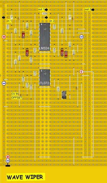
| Posted: Fri Jan 13, 2012 1:50 pm Post subject:
tuning the Wiper |
|
|
For those brave enough to try it, here's how to test and set the 47K trimpot:
Don't connect any signals to the inputs (incl. CV), better yet connect them to GND.
Turn the trimpot to it's minimum resistance, and the 100K "WIPE" pot to -12V.
You should measure a voltage of roughly +2V on OUT 1 and OUT 2. Now turn
the "WIPE" pot to +12V and measure the outputs, they should now be roughly -2V.
(if you measured a voltage way above and below 2V you could have the
trimpot turned the wrong way. else you need to check the circuit.)
Next, with the "WIPE" pot still at +12V turn the trimpot so that both outputs
are 0V. Now turn the "WIPE" pot back to -12V, the outputs should stay at 0V.
adjust the 47K trimpot if necessary. that's it (at least for now)
note: the circuit should work fine on +/-15V but you might want to
increase the 220K resistor attached to the "WIPE" pot.
_________________
"My perf, it's full of holes!"
http://phobos.000space.com/
SoundCloud BandCamp MixCloud Stickney Synthyards Captain Collider Twitch YouTube |
|
|
Back to top
|
|
|
emdot_ambient
Joined: Nov 22, 2009
Posts: 667
Location: Frederick, MD
|
| Posted: Fri Jan 13, 2012 1:58 pm Post subject:
|
|
|
| vladosh wrote: | | I already cut a piece of stripboard |
[greedy design thief] Don't forget to share the stripboard design! [/greedy design thief]
_________________
Looking for a certain ratio since 1978 |
|
|
Back to top
|
|
|
PHOBoS
Joined: Jan 14, 2010
Posts: 5907
Location: Moon Base
Audio files: 709
|
| Posted: Fri Jan 13, 2012 2:32 pm Post subject:
|
|
|
some more tests in case you don't have a scope and can't see if it's
working correct:
CV source connected to IN1 (pot between +/- 5V is useful for testing)
"WIPE" pot at +12V
OUT1 should follow IN1, OUT2 should be 0V
"WIPE" pot at -12V:
OUT1 should be 0V, OUT2 should follow IN1
CV source connected to IN2
"WIPE" pot at +12V:
OUT1 should be 0V, OUT2 should follow IN2
"WIPE" pot at -12V:
OUT1 should follow IN2, OUT2 should be 0V
for a final test you can connect a DC voltage to IN1 and a different voltage
to IN2. With the "WIPE" pot you should be able to control the outputs
between these voltages (where OUT2 does the opposite of OUT1).
_________________
"My perf, it's full of holes!"
http://phobos.000space.com/
SoundCloud BandCamp MixCloud Stickney Synthyards Captain Collider Twitch YouTube |
|
|
Back to top
|
|
|
vladosh
Joined: Aug 02, 2010
Posts: 679
Location: macedonia
Audio files: 51
|
|
|
Back to top
|
|
|
PHOBoS
Joined: Jan 14, 2010
Posts: 5907
Location: Moon Base
Audio files: 709
|
|
|
Back to top
|
|
|
vladosh
Joined: Aug 02, 2010
Posts: 679
Location: macedonia
Audio files: 51
|
| Posted: Sat Jan 14, 2012 6:32 am Post subject:
|
|
|
heh :/
thanks for checking the layout Phobos , i always do that kind of stuff and then wonder .. |
|
|
Back to top
|
|
|
|

 Forum index » DIY Hardware and Software