| Author |
Message |
Spikes
Joined: Feb 10, 2012
Posts: 14
Location: London, UK
|
 Posted: Fri Feb 10, 2012 3:50 am Post subject: Posted: Fri Feb 10, 2012 3:50 am Post subject:
|
  |
|
Hi all
This is my first post here.
Have just got a DB60XG from doublefish, there was an issue but it was sorted out quickly, great ebayer, buy with confidence etc.
Have seen several projects about using this board as a stand alone synth, which is what I want to do, but where to start?
Would I be correct in thinking that the PCBs earlier in this thread will work for the DB60XG? And "all" that is required is to send some sysex messages and from then on regular program change?
Sorry if this is a bit newbie, but we all got to start somewhere.
Thanks guys
Spikes |
|
|
Back to top
|
|
 |
Dan Lavin

Joined: Nov 09, 2006
Posts: 649
Location: Spring Lake, Mi, USA
Audio files: 21
|
| Posted: Fri Feb 10, 2012 3:35 pm Post subject:
|
|
|
yes, correct. your board will work just fine as a GM Voice. I have the same board from doublefish and the pinout is compatible. have fun.
_________________
Synth DIY since 1977! |
|
|
Back to top
|
|
|
Spikes
Joined: Feb 10, 2012
Posts: 14
Location: London, UK
|
| Posted: Thu Feb 16, 2012 1:07 am Post subject:
|
|
|
Thanks Dan, only other question I have at the moment is does the DB60XG require a sysex message before any sound can be produced? If so, can you tell me what it is?
Not really important but couldn't find an asnwer to this.
Thanks again
Spikes |
|
|
Back to top
|
|
|
Spikes
Joined: Feb 10, 2012
Posts: 14
Location: London, UK
|
| Posted: Sat Mar 31, 2012 10:14 am Post subject:
|
|
|
It works!
Pretty much first go, the regulators are getting hot but a heatsink should sort that out.
It is better than very good! |
|
|
Back to top
|
|
|
Dan Lavin
Joined: Nov 09, 2006
Posts: 649
Location: Spring Lake, Mi, USA
Audio files: 21
|
| Posted: Sat Mar 31, 2012 11:55 am Post subject:
|
|
|
Spikes,
Congrats!
| Quote: | | does the DB60XG require a sysex message before any sound can be produced? |
Yes and No. Without it, it will fire up as a GM module. If you send the XG sysex message, it will become XG compatible. I'm not sure what that message is, but I believe someone in this forum posted it. The message can be sent by a sequencer or some of the newer controllers will allow it.
_________________
Synth DIY since 1977! |
|
|
Back to top
|
|
|
Quintus
Joined: Feb 20, 2011
Posts: 13
Location: UK
|
| Posted: Sun Apr 01, 2012 1:50 am Post subject:
|
|
|
The reg does run hot and I now use low drop out reg instead of the 78 series
The code for XG reset is
F0 43 10 4C 00 00 7E 00 F7 (hex)
The module should start in XG mode on power-up.
You can send this by MIDI OX. XGGold is the best DB50XG computer controller there is a trial version for free. The DB50XG manual is available here:
http://www.yamaha.co.jp/manual/english
or Google
Quintus |
|
|
Back to top
|
|
|
Spikes
Joined: Feb 10, 2012
Posts: 14
Location: London, UK
|
| Posted: Sun Apr 01, 2012 1:23 pm Post subject:
|
|
|
Thanks for the replies chaps, am pleased to report that the heatsink on the 7805 worked and have been messing about with the voices etc.
The QS3000 voice thing is now puzzling me, tried using XG Gold but it doesn't seem to upload anything, does this only work in a registered version?
Is there any other way to load those QVB files?
Once loaded do these sounds remain on board or do they have to be uploaded every time?
Thanks again
Spikes |
|
|
Back to top
|
|
|
Spikes
Joined: Feb 10, 2012
Posts: 14
Location: London, UK
|
| Posted: Sat Apr 14, 2012 7:27 am Post subject:
|
|
|
And now it doesn't work! 
Well thats not quite right, I rewired it as I wanted to add it into a set up, now I only get audio output when I touch any analogue ground, obviously this is a grounding issue, but anyone got any suggestions how to cure this?
Thanks. |
|
|
Back to top
|
|
|
Spikes
Joined: Feb 10, 2012
Posts: 14
Location: London, UK
|
| Posted: Sat Apr 14, 2012 1:27 pm Post subject:
|
|
|
Well looking at it there was a rather long Analogue Ground wire, shortened that and all is good again  |
|
|
Back to top
|
|
|
neuweiler
Joined: Jan 12, 2010
Posts: 5
Location: Switzerland
|
| Posted: Sat May 12, 2012 3:14 pm Post subject:
My DB60 Box |
|
|
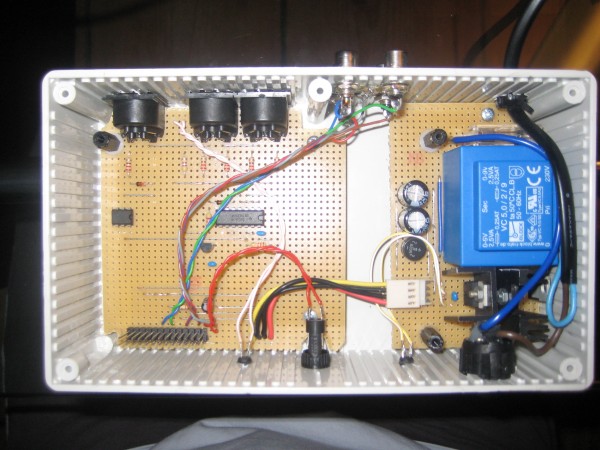
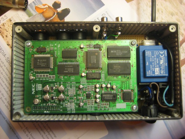
After posting a pdf with a perfboard layout (see bottom on page 9), I owe you some pics of the finished product.
"Reduced to the max"
NOTE: I anyone could tell me what needs to be done in order to get an spdif output (optical or coax), I'd be very grateful!
| Description: |
|
| Filesize: |
2.82 MB |
| Viewed: |
1025 Time(s) |
| This image has been reduced to fit the page. Click on it to enlarge. |
|
| Description: |
|
| Filesize: |
3.26 MB |
| Viewed: |
1016 Time(s) |
| This image has been reduced to fit the page. Click on it to enlarge. |
|
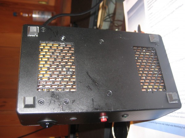
| Description: |
| some vent louvers on the bottom side (for better passive cooling) |
|
| Filesize: |
2.96 MB |
| Viewed: |
950 Time(s) |
| This image has been reduced to fit the page. Click on it to enlarge. |
|
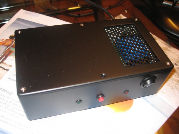
| Description: |
| and the box from top (labels still missing) |
|
| Filesize: |
2.19 MB |
| Viewed: |
895 Time(s) |
| This image has been reduced to fit the page. Click on it to enlarge. |
|
|
|
|
Back to top
|
|
|
elmegil

Joined: Mar 20, 2012
Posts: 2179
Location: Chicago
Audio files: 16
|
| Posted: Sat May 12, 2012 7:26 pm Post subject:
|
|
|
How did you get the grille so nice and even? That looks awesome. Makes me feel really bad about the cruddy 6 3/8" drill holes I used to ventilate a power supply I made
I'm assuming you were using a dremel? But even so I don't think I could ever be so even handed...
Edit: oh wait, those grilles aren't drilled into the actual project box, are they?  |
|
|
Back to top
|
|
|
neuweiler
Joined: Jan 12, 2010
Posts: 5
Location: Switzerland
|
| Posted: Wed May 16, 2012 11:26 pm Post subject:
|
|
|
| Ah no, these are no drill holes. Had the same idea at first but then decided that I was never able to get a nice grille this way. I took a piece of a plastic to protect the drip rail from leaves (http://img.westfalia.de/media/show_image.php?datei_id=687) , sprayed it black and glued it in from the inside. You can still do it that way, just cut out the area with a knife and rasp the edge clean. |
|
|
Back to top
|
|
|
wmonk
Joined: Sep 15, 2008
Posts: 529
Location: Enschede, the Netherlands
Audio files: 15
|
| Posted: Thu May 17, 2012 4:25 am Post subject:
|
|
|
I see you used one of those small transformers. Can you give some information of how you did that and if it gives enough power for the whole thing?
_________________
Weblog! |
|
|
Back to top
|
|
|
magman
Joined: Feb 04, 2009
Posts: 363
Location: Liverpool, UK
|
| Posted: Fri May 18, 2012 7:54 am Post subject:
|
|
|
Actually, looking at your mains PSU in a bit more detail, have you got any insulation between the Veroboard and the perforated sheet?
It looks like you have connected live mains via a switch and fuse to the input of the PCB mounted transformer on the Veroboard. This means there are some Veroboard tracks at mains potential very close to the open mesh. If you are unlucky enough to put the module down on something metallic with something that can just stick up through the grill (such as studs on the back of a panel, or a spiky heatsink), you have a reasonable chance of making this metal live to the mains. 
Always treat mains power with the respect that you would treat anything that could kill you. You would want some protection between a Lion and you in a Zoo, do the same between mains electricity and Murphy's Law.
If you have a clear insulator in there, fine - but it's better to be safer than sorry, hence my query.
Regards
Magman |
|
|
Back to top
|
|
|
neuweiler
Joined: Jan 12, 2010
Posts: 5
Location: Switzerland
|
| Posted: Sat May 19, 2012 9:11 am Post subject:
|
|
|
| wmonk wrote: | | I see you used one of those small transformers. Can you give some information of how you did that and if it gives enough power for the whole thing? |
Yes, I used a transformer with two secondary windings. They each output 9V with 2.5VA. As this wouldn't be enough, I connected the two windings and use them in series - to get approx. 18V.
As you can see in img_6792.jpg, the transformer has outputs on pins 6+7 and 9+10. On page 9 of this thread in Waveblaster-Midi-Layout.pdf you can see, that I short connected pin 7 and 9. This way I get 18V on pin 6 and 10 and GND on pin 7+9 (grey circuit paths). The output of pin 6 and 10 are routed to a bridge rectifier.
As the draw on +5V is the highest and as I get +5V from the +12V, the 7812 and 7805 get a little hot without heat sink. So I added one to each - although it got a bit cramped in that area. All other parts, even the transformator, remain quite cool.
| magman wrote: | | Actually, looking at your mains PSU in a bit more detail, have you got any insulation between the Veroboard and the perforated sheet? |
Oops, you're absolutely right! I only insulated the top parts but not the underside of the board. Luckily the output of the fuse and the input of the transformer are a bit away from the opening - but the input of the fuse is visible. I will insulate everything though. Thanks a lot for the hint!
At first I had no grille there and the liberaly cut out parts in the circuit path would have been enough to prevent unwanted high voltage on other paths. But when I cut out the 2nd hole on the underside, I didn't think about it anymore. |
|
|
Back to top
|
|
|
sompost
Joined: Aug 17, 2010
Posts: 58
Location: Switzerland
|
| Posted: Tue Jun 19, 2012 2:09 am Post subject:
I got mine, sort of... |
|
|
I just got my DB60XG from double-fish1981! Unfortunately, it appeared to have got a rough treatment during transport: several SMD electrolytic capacitors are damaged, and one is partially and another one completely torn off. I guess that they are decoupling capacitors -- the meat of the beast being in the ICs -- so the board might just work without them.
Perhaps I could solder on ordinary electrolytic capacitors, and then lay them flat on the board, but I like things neat and tidy. So I ordered SMD ones and then cross my fingers that the rest of the board didn't suffer too much.
Even though a dollar isn't what it used to be, 25 of them are still roughly $25 after all, aren't they.
Ralph
_________________
Built: MFOS SLMS plus, SL Ultimate & Expander, 10 step seq; SLMS MkII; PAiA FatMan, Mutable-Instruments Shruthi-1; Jasper Wasp Clone
Building: Maddox MonoWave; Auduino; ASM-2; Minimoog Clone
Backlogging: MFOS 16 step seq; TH SN Voice; Takeda One Board Farm; Okita Vocoder; Page TR-9090; TH GM Voice, AY Voice |
|
|
Back to top
|
|
|
Silesius

Joined: Feb 12, 2010
Posts: 65
Location: Berlin
|
| Posted: Wed Jun 20, 2012 4:08 am Post subject:
|
|
|
| Hi! Just a quick question. I have all the parts needed for the project, but I couldn't find the 74ls00. I just assumed it would work with a CMOS 4093 nand gate. I haven't started yet, but it would be nice to know if my idea is correct. What do you think guys? |
|
|
Back to top
|
|
|
Silesius
Joined: Feb 12, 2010
Posts: 65
Location: Berlin
|
| Posted: Thu Jun 21, 2012 2:30 am Post subject:
|
|
|
| Well, it's not working for me; but as I said, I'm using a 4093 nand gate; I think everything else is fine so, before assuming my board is faulty, I would like to know if this is supposed to work with cmos gates instead of ttl. Any ideas concerning this?? |
|
|
Back to top
|
|
|
sompost
Joined: Aug 17, 2010
Posts: 58
Location: Switzerland
|
| Posted: Thu Jun 21, 2012 4:16 am Post subject:
|
|
|
The 4093 is not actually a NAND gate but a NAND Schmitt Trigger. Could that be the problem? I'm not too proficient in electronics, so I couldn't tell (that's why I usually follow instructions to the letter )
If it doesn't work, try leaving out the NAND altogether. The circuit published by c't (http://www.heise.de/ct/artikel/MIDImal-285418.html) doesn't do any buffering at all, so I don't think it's strictly required.
Ralph
_________________
Built: MFOS SLMS plus, SL Ultimate & Expander, 10 step seq; SLMS MkII; PAiA FatMan, Mutable-Instruments Shruthi-1; Jasper Wasp Clone
Building: Maddox MonoWave; Auduino; ASM-2; Minimoog Clone
Backlogging: MFOS 16 step seq; TH SN Voice; Takeda One Board Farm; Okita Vocoder; Page TR-9090; TH GM Voice, AY Voice |
|
|
Back to top
|
|
|
Spikes
Joined: Feb 10, 2012
Posts: 14
Location: London, UK
|
| Posted: Fri Jul 13, 2012 11:47 pm Post subject:
|
|
|
| Try a 74HC00, other designs use this. Yes it is an important part of the circuit as the daughter board expects MIDI data to be at a TTL level. |
|
|
Back to top
|
|
|
mjkirk12

Joined: Jan 05, 2009
Posts: 22
Location: Chicago, IL USA
|
Posted: Wed Feb 13, 2013 2:21 pm Post subject:
Yamaha DB60XG and XG Gold
Subject description: 3 and 4 element voices work for anyone? |
|
|
I was wondering if anyone has good results with the licensed XG Gold software and Yamaha DB60XG card for the "hidden" QS300 patches that use 3 and 4 element voicings?
The unlicensed XG Gold only supports 1 or 2 element voicings.
I configure the DB60XG for a 3 or 4 element patch, click the QS editor, and reduce the volume on elements 1 and 2, and get no sound. I would expect to hear something with elements 3 and 4 levels turned up.
Maybe I need to take this up with the XG Gold author as a next step, but wanted to make sure someone else has this already working on a DB60XG (or DB50XG).
Thanks,
Mike |
|
|
Back to top
|
|
|
mjkirk12
Joined: Jan 05, 2009
Posts: 22
Location: Chicago, IL USA
|
Posted: Wed Feb 13, 2013 8:11 pm Post subject:
Yamaha DB60XG and XG Gold
Subject description: 3 and 4 element voices work for anyone? |
|
|
Problem fixed. I am able to get 3/4 element voices on DB60XG working.
1) XG Gold must have TC (transmit as controller) button DESELECTED. The 'hidden' QS300 voices must use Sysex messages instead of CC (controller) messages with 3/4 element voices to set volume and other parameters.
2) I was routing the XG Gold through MIDI-OX with small Sysex buffer (256 bytes) which also seems to cause problems. When I ran XG Gold direct to the DB60XG it works fine. Later in MIDI-OX, I enlarged to 512 byte Sysex buffers and decreased the Sysex message latency which seems to work for me.
Thanks,
Mike |
|
|
Back to top
|
|
|
Dan Lavin
Joined: Nov 09, 2006
Posts: 649
Location: Spring Lake, Mi, USA
Audio files: 21
|
| Posted: Sat Mar 08, 2014 1:00 pm Post subject:
|
|
|
For those looking for a more updated soundcard to use, I've posted my GM Voice for the 21st Century in the main DIY section here:
http://electro-music.com/forum/topic-61315.html
The circuitry is also a lot more simple than this design, making it an ideal 1st time DIY project.
_________________
Synth DIY since 1977! |
|
|
Back to top
|
|
|
Dan Lavin
Joined: Nov 09, 2006
Posts: 649
Location: Spring Lake, Mi, USA
Audio files: 21
|
| Posted: Tue Jul 01, 2014 11:24 am Post subject:
|
|
|
I just posted in the Arduino sub-forum a way to make the GM Voice respond to a single midi channel instead of all midi channels. Should be easier to work with other midi modules:
http://electro-music.com/forum/post-401253.html#401253
_________________
Synth DIY since 1977! |
|
|
Back to top
|
|
|
sompost
Joined: Aug 17, 2010
Posts: 58
Location: Switzerland
|
| Posted: Wed Jan 07, 2015 12:46 am Post subject:
Comatose DB60XG clone... |
|
|
Hi everyone!
Sorry for infusing new life in an old thread. I wish I could do that with a DB60XG clone (NEC XR385) that stopped working after I left it sitting around for a year or so.
When I ordered it, I had to replace 2 of the 10uF capacitors, because they were ripped off during transport. After that, it worked perfectly. I could play the GM voices and even verify that I could upload and play QS300 voices. The circuit I use to attach the board to is a blend of various designs here on this thread.
I went on to implement a PSR-type style player, which took a while (always does...) and when I wanted to test an early version of it. The board was completely silent. It appears the the audio output is zero.
I have a second board where I can hear "something" through the intense crackling noise when I play it using a MIDI keyboard, suggesting that the circuits leading to (MIDI/power) and from the board (audio amp using a TL072) are somewhat OK.
I wonder if anyone could hint at what might be the problem (no sound on one board, crackling on the other). I checked voltages as far as I know where to look, and so far it looks good. Of course I can't fix/replace any of the ICs, but I might go ahead and replace all the electrolytic capacitors (some of which have dents), if that makes any sense at all.
Any ideas as to what I -- a borderline dilettante -- might check are most welcome!
Thanks, Ralph
_________________
Built: MFOS SLMS plus, SL Ultimate & Expander, 10 step seq; SLMS MkII; PAiA FatMan, Mutable-Instruments Shruthi-1; Jasper Wasp Clone
Building: Maddox MonoWave; Auduino; ASM-2; Minimoog Clone
Backlogging: MFOS 16 step seq; TH SN Voice; Takeda One Board Farm; Okita Vocoder; Page TR-9090; TH GM Voice, AY Voice |
|
|
Back to top
|
|
|
|

 Forum index » DIY Hardware and Software » Thomas Henry designs
