| Author |
Message |
LektroiD

Joined: Aug 23, 2008
Posts: 1019
Location: Scottish Borders
Audio files: 2
G2 patch files: 2
|
 Posted: Tue Mar 13, 2012 12:46 pm Post subject: Posted: Tue Mar 13, 2012 12:46 pm Post subject:
|
  |
|
I just got hold of the suggested transistors, but my build is dead (both sides)... I tried a few different 4011's just in case. unfortunately I only had the two CA3086's, so I can't replace them.
The only thing I can think of is due to not having installed the pots (it's the only thing left). I presumed it would work without them, but I can't find which values to put in, or if there's any particular wiring that needs to be done (ie. the wiper shorted to the outer lug, etc.).
Other than that, I used fixed resistors in place of the tempcos (just to get it started), but thought that would only affect scaling, and not render it flatlined.
If anyone has a BOM, or wiring diagram they could post, that would be awesome, although I have a feeling this won't fix my dead oscillator.
If anyone could shed some light on this.. where to scope it out and what to expect where. I don't know where else to look. |
|
|
Back to top
|
|
 |
LetterBeacon
Joined: Mar 18, 2008
Posts: 454
Location: London, UK
|
| Posted: Tue Mar 13, 2012 12:55 pm Post subject:
|
|
|
| AndyR1960 wrote: |
6. I used 100k Lin for all the controls... ARP used 100k Log for the FM attenuators.
Andy. |
I believe (and it's been a long time since I built it) that you wire the coarse pad to the wiper of the pot, and then -15 to the CCW lug and the +15 to the CW lug.
I think I posted a BOM earlier in the thread somewhere.
EDIT - here it is: http://electro-music.com/forum/post-212939.html#212939 |
|
|
Back to top
|
|
|
LektroiD
Joined: Aug 23, 2008
Posts: 1019
Location: Scottish Borders
Audio files: 2
G2 patch files: 2
|
| Posted: Wed Mar 14, 2012 5:08 am Post subject:
|
|
|
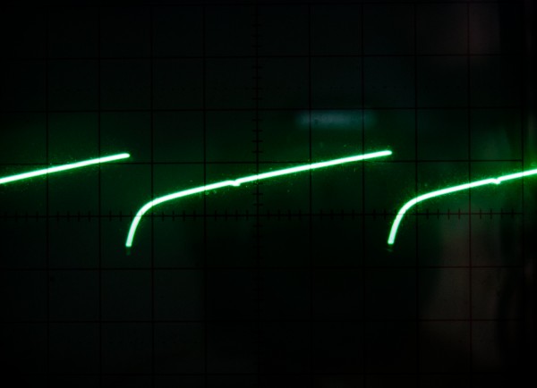
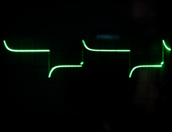
I got it sort of working.. However, the 'scope is showing some obscure artefacts (on both VCO 1&2)..
Any way I can flatten these spikes?
| Description: |
|
| Filesize: |
814.56 KB |
| Viewed: |
507 Time(s) |
| This image has been reduced to fit the page. Click on it to enlarge. |
|
| Description: |
|
| Filesize: |
577.42 KB |
| Viewed: |
468 Time(s) |
| This image has been reduced to fit the page. Click on it to enlarge. |
|
|
|
|
Back to top
|
|
|
LektroiD
Joined: Aug 23, 2008
Posts: 1019
Location: Scottish Borders
Audio files: 2
G2 patch files: 2
|
| Posted: Thu Mar 15, 2012 4:40 am Post subject:
|
|
|
I just noticed the higher frequency the narrower the pulse width (and even at the lowest frequency, neither oscillator quite manages square). I'm sure that's not supposed to happen.
I wonder what is causing those tails (pictured above), and if that is related?
Any suggestions welcomed. |
|
|
Back to top
|
|
|
chok
Joined: May 18, 2008
Posts: 26
Location: Nogent sur marne/France
|
| Posted: Sun Apr 08, 2012 2:34 am Post subject:
|
|
|
Hello to all
I follow this thread with attention because I am preparing exactly a cloning of the oscillators of Odyssey ( MK2). For the used tempco, seen that 1k87 is not a value spread in Europe, I wondered if we put a tempco of 1k with a resistance approaching 870 ohms could work.... I plan to use only the heart of the VCO, just the sawtooth output, the purpose being to make rather small hybrid modules... Of what do you think of it?
Edit: after viewing all answers, I find..  |
|
|
Back to top
|
|
|
steffensen

Joined: Jul 11, 2012
Posts: 103
Location: Sweden
|
| Posted: Mon Jul 16, 2012 8:32 am Post subject:
|
|
|
Been a ARP fan for the last 15 years or so, and been looking for a DIY way to recreate some of this magic. Then i stumble on to this, which sounds amazing!
As im euro-based, im curious on the question asked already, if theres any way to make this work in my euro case? I would get a 5v adapter if needed, but making it work solely on 12v would be preferred.
Any PCB's around for this project? (im not there yet, where i have the option to etch my own)
Again, this really sounded good. Been looking hard for a VCO that did it for me, and havent found many tbh. This one tho.. amazing stuff! |
|
|
Back to top
|
|
|
Broadwave

Joined: Feb 16, 2007
Posts: 347
Location: Manchester UK
Audio files: 6
|
| Posted: Mon Jul 23, 2012 11:49 pm Post subject:
|
|
|
Sorry it's taken so long, but here's the single Eurorack version of the Odyssey MkII/III VCO. 
I've built several (5!) and have had no problems with them except that, when I mount them in my grounded rack, the pitch drops about half a semitone!!! Still not sure what's causing this, but once it's in the rack and tuned up, it's perfectly fine.
Again, like the dual version, the FM inputs are "floating" (the Odyssey always has a voltage at the FM input) so please make sure that the input pot is always counter clockwise when not in use, otherwise you will encounter scaling problems.
OK, I'll admit it's a bit of a hack, but it works.
I'm not releasing the 2600 VCO/Waveshaper yet as:
a) It's already been posted here
b) Too many kludges in the pulse width pot wiring (ie. messy!)
The schematic can be found via Google (ARP Service Manual), and please remember that I'm just an enthusiast, with no formal electronics training... so if there's a problem, I may not be able to help... but I'll try
Hope you find it useful.
Oh... and before I forget. The Ring Mod is NOT included on this board, but a 0-10v Square Wave output is provided to feed the ARP's XOR Ring Mod (I'm working on it, and I'll post ASAP), but it's a simple circuit that can be built on strip board fairly easily.
| Description: |
|

Download (listen) |
| Filename: |
ARP Odyssey VCO Foil.pdf |
| Filesize: |
99.92 KB |
| Downloaded: |
1700 Time(s) |
| Description: |
|
Download (listen) |
| Filename: |
ARP Odyssey VCO Layout.pdf |
| Filesize: |
394.74 KB |
| Downloaded: |
1794 Time(s) |
_________________
Kronos 2-88, Kronos 61, Studiologic Sledge V2/SL, Broadwave ARP 2600EX, Broadwave 18U ARP based Eurorack Modular, Broadwave Minimoog Clone, GEM S2 Turbo.
Synth DIY Projects
Musical Doodlings |
|
|
Back to top
|
|
|
Broadwave
Joined: Feb 16, 2007
Posts: 347
Location: Manchester UK
Audio files: 6
|
| Posted: Tue Jul 24, 2012 2:12 am Post subject:
|
|
|
| LektroiD wrote: | | I just noticed the higher frequency the narrower the pulse width (and even at the lowest frequency, neither oscillator quite manages square). I'm sure that's not supposed to happen. |
I have to admit that I'm flummoxed. Both VCO's have the same problem?
The only common thing that I can think of off the top of my head is either the 4011 or the +/-15v power supply (they're common to both VCO's) so I would start there, I would also make sure that any flux is cleaned off - I've had numerous problems with flux residue in the past, I now use a water soluble flux based solder, and just clean the back off with water and a soft toothbrush!
I wish I could be of more help... But I'll continue scratching my head over this one.
_________________
Kronos 2-88, Kronos 61, Studiologic Sledge V2/SL, Broadwave ARP 2600EX, Broadwave 18U ARP based Eurorack Modular, Broadwave Minimoog Clone, GEM S2 Turbo.
Synth DIY Projects
Musical Doodlings |
|
|
Back to top
|
|
|
steffensen
Joined: Jul 11, 2012
Posts: 103
Location: Sweden
|
| Posted: Tue Jul 24, 2012 5:25 am Post subject:
|
|
|
| AndyR1960 wrote: | Sorry it's taken so long, but here's the single Eurorack version of the Odyssey MkII/III VCO.
I've built several (5!) and have had no problems with them except that, when I mount them in my grounded rack, the pitch drops about half a semitone!!! Still not sure what's causing this, but once it's in the rack and tuned up, it's perfectly fine.
Again, like the dual version, the FM inputs are "floating" (the Odyssey always has a voltage at the FM input) so please make sure that the input pot is always counter clockwise when not in use, otherwise you will encounter scaling problems.
OK, I'll admit it's a bit of a hack, but it works.
I'm not releasing the 2600 VCO/Waveshaper yet as:
a) It's already been posted here
b) Too many kludges in the pulse width pot wiring (ie. messy!)
The schematic can be found via Google (ARP Service Manual), and please remember that I'm just an enthusiast, with no formal electronics training... so if there's a problem, I may not be able to help... but I'll try
Hope you find it useful.
Oh... and before I forget. The Ring Mod is NOT included on this board, but a 0-10v Square Wave output is provided to feed the ARP's XOR Ring Mod (I'm working on it, and I'll post ASAP), but it's a simple circuit that can be built on strip board fairly easily. |
Thank you so much for these!
Been waiting so long for such detailed guide/layout.
Do you happen to know if the designed changed a lot from the MK I and MK II?
I love that "moogish" ARP sound, and if it meant just some small changes (that i could do myself) i would do it.
From my understanding the VCO from the 2600 and Odyssey were the same ones, with the difference that the 2600 had some waveshapers to form more waveforms. This means i should be able to base my 2600 obsession with this VCO as a starter. |
|
|
Back to top
|
|
|
Broadwave
Joined: Feb 16, 2007
Posts: 347
Location: Manchester UK
Audio files: 6
|
| Posted: Tue Jul 24, 2012 7:06 am Post subject:
|
|
|
The design from the MkI to the MkII/III is very different. I've built both and it's my opinion that the MKI is certainly not as stable, but the saw output is a downward ramp as opposed to the MKIII's which is up... sonically there's no difference.
VCO 1 on the Odyssey can be switched to low frequency mode as a modulation source, and that's where the main change is... I'd much rather have a down ramp as a mod source than the other way.
The VCO core is the same for the later 2600's (Module 4027-1), but there are a few component changes that I've noticed which I presume is to get the raw saw output to 0-10V (as opposed the the Oddy's 0-5V), to feed the wave shapers.
_________________
Kronos 2-88, Kronos 61, Studiologic Sledge V2/SL, Broadwave ARP 2600EX, Broadwave 18U ARP based Eurorack Modular, Broadwave Minimoog Clone, GEM S2 Turbo.
Synth DIY Projects
Musical Doodlings |
|
|
Back to top
|
|
|
steffensen
Joined: Jul 11, 2012
Posts: 103
Location: Sweden
|
| Posted: Tue Jul 24, 2012 9:43 am Post subject:
|
|
|
| AndyR1960 wrote: | The design from the MkI to the MkII/III is very different. I've built both and it's my opinion that the MKI is certainly not as stable, but the saw output is a downward ramp as opposed to the MKIII's which is up... sonically there's no difference.
VCO 1 on the Odyssey can be switched to low frequency mode as a modulation source, and that's where the main change is... I'd much rather have a down ramp as a mod source than the other way.
The VCO core is the same for the later 2600's (Module 4027-1), but there are a few component changes that I've noticed which I presume is to get the raw saw output to 0-10V (as opposed the the Oddy's 0-5V), to feed the wave shapers. |
Ah, explains a lot i guess then. I always found the MK I more punchy than compared to later versions.
I do feel the sound of your build to be awesome tho, so MK II would be enough on my part. However, the Ramp Down version is tempting as well.
The 2600 VCO linked above, isnt that clear to build imo. Not for a hobbyist like me anyway. I wouldnt mind a clear guide to that one, similar to your MK II/III.
Time to start sourcing components!  |
|
|
Back to top
|
|
|
frequencycentral

Joined: May 25, 2008
Posts: 186
Location: UK
|
| Posted: Tue Jul 24, 2012 11:37 am Post subject:
|
|
|
Thanks so much for posting the layouts Andy, been itching to build me some ARP VCOs. Actually, I'm spoilt, since I have a whiteface MkI, but hey, how many VCOs is too many?
_________________
http://www.frequencycentral.co.uk/ |
|
|
Back to top
|
|
|
steffensen
Joined: Jul 11, 2012
Posts: 103
Location: Sweden
|
| Posted: Wed Jul 25, 2012 7:50 am Post subject:
|
|
|
@AndyR1960 (or anyone in the knows)
My local shop have most of the stuff i need for this (besides the really rare parts), so i wonder, would these parts be decent enough/work as replacements?
For the 680pf (Polystyrene/ Silvered Mica preferred it seems):
This - Polypropylen Wima FKP2 poly 680pF 100V 2.5%
Or perhaps this - Polystyrene 1000pF 50V 5%
For the 2N5459, would this work instead - BF247A TO-92 N-ch 25V 80mA
http://www.datasheetcatalog.org/datasheet/philips/BF246C.pdf
(i have found a source for this, but it would still be good to know for future builds)
And for the 2N5910, perhaps this would work - PN2907 TO-92 PNP 60V 0.8A
http://www.datasheetcatalog.org/datasheet/fairchild/PN2907.pdf |
|
|
Back to top
|
|
|
Sebo

Joined: Apr 27, 2007
Posts: 564
Location: Argentina
|
| Posted: Wed Jul 25, 2012 9:25 am Post subject:
|
|
|
Hi:
I originally used 1000pF styroflex for the timing capacitor, but to tunning was 4 octaves lower than expected, I added a 390K resistor from 15V to the CV summing node to compensate, but this makes the exponentiator reaches the non-linear zone (or linear is a better therm in this case) earlier, so the good tunning was limited to 5 octaves. I changed the cap to 680pF styroflex and took away the resistor and now I have about 10 octaves of goog tunning.
For the 2N5459 I originally used BF245 (the pinout is reversed), then changed for the 2N5459, I didn't note any difference.
For the 2N5910 I used 2N3906.
Also I used 2K tempcos.
Hope this help.
_________________
Sebo
---------------------------------------
My Music:
https://www.facebook.com/cosaquitos/ |
|
|
Back to top
|
|
|
steffensen
Joined: Jul 11, 2012
Posts: 103
Location: Sweden
|
| Posted: Wed Jul 25, 2012 9:35 am Post subject:
|
|
|
| Sebo wrote: | Hi:
I originally used 1000pF styroflex for the timing capacitor, but to tunning was 4 octaves lower than expected, I added a 390K resistor from 15V to the CV summing node to compensate, but this makes the exponentiator reaches the non-linear zone (or linear is a better therm in this case) earlier, so the good tunning was limited to 5 octaves. I changed the cap to 680pF styroflex and took away the resistor and now I have about 10 octaves of goog tunning.
For the 2N5459 I originally used BF245 (the pinout is reversed), then changed for the 2N5459, I didn't note any difference.
For the 2N5910 I used 2N3906.
Also I used 2K tempcos.
Hope this help. |
That helped a lot, thanks!
I have ordered some 2N5459's already, but now i have at least 2 replacements to use if those dont turn up. Great.
Also planned to go with the 2N3906 instead of 2N5910, as those are just too hard to find. Might replace it with the "proper" one some day tho, when/if i find it.
Last part (i think), is the 2k TempCo, but im closing in on those i think. |
|
|
Back to top
|
|
|
Broadwave
Joined: Feb 16, 2007
Posts: 347
Location: Manchester UK
Audio files: 6
|
| Posted: Thu Jul 26, 2012 11:07 pm Post subject:
|
|
|
+1 to everything that Sebo mentioned. : )
_________________
Kronos 2-88, Kronos 61, Studiologic Sledge V2/SL, Broadwave ARP 2600EX, Broadwave 18U ARP based Eurorack Modular, Broadwave Minimoog Clone, GEM S2 Turbo.
Synth DIY Projects
Musical Doodlings |
|
|
Back to top
|
|
|
steffensen
Joined: Jul 11, 2012
Posts: 103
Location: Sweden
|
| Posted: Fri Jul 27, 2012 2:56 am Post subject:
|
|
|
I decided to go with the Wima 680pf, it should work fine i guess.
Done a lot of research on this and it seems to be commonly used for audio products today, + i saw you using the Wima yourself Andy? |
|
|
Back to top
|
|
|
frequencycentral
Joined: May 25, 2008
Posts: 186
Location: UK
|
|
|
Back to top
|
|
|
brother303

Joined: Nov 02, 2010
Posts: 139
Location: ruhr-area/germany
|
| Posted: Tue Aug 14, 2012 8:46 am Post subject:
|
|
|
Hi Rick,
are you offering a run of pcbs for those puppies?
Cheers
Greg
_________________
Best regards
Greg |
|
|
Back to top
|
|
|
frequencycentral
Joined: May 25, 2008
Posts: 186
Location: UK
|
| Posted: Tue Aug 14, 2012 8:55 am Post subject:
|
|
|
| brother303 wrote: | Hi Rick,
are you offering a run of pcbs for those puppies?
Cheers
Greg |
I hadn't considered it, those in the photo are for me and a buddy. I guess with Andy's permission I'd offer them.
_________________
http://www.frequencycentral.co.uk/ |
|
|
Back to top
|
|
|
brother303
Joined: Nov 02, 2010
Posts: 139
Location: ruhr-area/germany
|
| Posted: Wed Aug 15, 2012 12:23 am Post subject:
|
|
|
Hi,
a run of pcbs would be awesome. I guess there will be some interest here and over at Muffs of course.
@AndyR : Please give Rick the permission to start a run.

Best regards
Greg
_________________
Best regards
Greg |
|
|
Back to top
|
|
|
frequencycentral
Joined: May 25, 2008
Posts: 186
Location: UK
|
| Posted: Wed Aug 15, 2012 12:58 am Post subject:
|
|
|
| brother303 wrote: | Hi,
a run of pcbs would be awesome. I guess there will be some interest here and over at Muffs of course.
@AndyR : Please give Rick the permission to start a run.
Best regards
Greg |
Andy has very kindly given his permission for me to do a run. He suggests that I build one first. PCBs will be £15 each. I've also designed a dual VCO panel which is 21HP. It includes a sync switch as well as additional socket for ring mod when the PCB appears. Panel will be £20.

_________________
http://www.frequencycentral.co.uk/ |
|
|
Back to top
|
|
|
Broadwave
Joined: Feb 16, 2007
Posts: 347
Location: Manchester UK
Audio files: 6
|
| Posted: Wed Aug 15, 2012 1:16 am Post subject:
|
|
|
Finally found the ARP Odyssey Ring Mod layout 
The artwork is the correct size, so please don't use the PDF "shrink to fit" when you print it out.
The board is made to directly mount Cliff 3.5 PCB sockets, but you can just directly wire the I/O's to whatever socket you're using.
Try Ring Mod with Sync... you'll be in Ultravox Heaven
Once again, this can be freely used.
Glad to help.
Andy
BTW - This is specific to the Odyssey VCO's RM out, and may not work with other square wave inputs (must be 0 to +10v square/pulse to work).
| Description: |
|
Download (listen) |
| Filename: |
ARP Ring XOR.pdf |
| Filesize: |
287.1 KB |
| Downloaded: |
1648 Time(s) |
_________________
Kronos 2-88, Kronos 61, Studiologic Sledge V2/SL, Broadwave ARP 2600EX, Broadwave 18U ARP based Eurorack Modular, Broadwave Minimoog Clone, GEM S2 Turbo.
Synth DIY Projects
Musical Doodlings |
|
|
Back to top
|
|
|
brother303
Joined: Nov 02, 2010
Posts: 139
Location: ruhr-area/germany
|
| Posted: Wed Aug 15, 2012 2:23 am Post subject:
|
|
|
Awesome,
that´s really fast! Thanks you Andy.
Rick,please count me in for 2x vco-pcb and 1x ringmod-pcb (when available).
Cheers
Greg
_________________
Best regards
Greg |
|
|
Back to top
|
|
|
stewpye
Joined: Apr 30, 2009
Posts: 49
Location: Brisbane, Australia
|
| Posted: Wed Aug 15, 2012 1:14 pm Post subject:
|
|
|
The suggestion by various people that the Odyssey sync was somewhat special sounding intrigued me so I checked out the schematics...
With the Odyssey VCO the sync input actually forces a fast completion of the discharge cycle, then once the normal threshold has been reached the oscillator resets. In a standard ENS76 type VCO with op amp integrator and comparator reset the sync input temporarily changes the reset threshold so that whatever point in the waveform its at the oscillator will just rest. It will not complete charge cycle.
So in the Odyssey VCO whenever sync is activated there would be a little "pip" in the waveform where it completes the discharge cycle. I assume this would be more obvious if the sync occurred early in the cycle, however it still may be hard to see on a scope.
I might try experimenting with an ENS76 type VCO to see if the same effect can be achieved by switching the input of the integrator to the negative rail with a FET.
Regards,
Stewart. |
|
|
Back to top
|
|
|
|

 Forum index » DIY Hardware and Software

