| Author |
Message |
ryktnk

Joined: Apr 24, 2008
Posts: 285
Location: london
Audio files: 1
|
 Posted: Sat May 23, 2020 1:25 am Post subject: Posted: Sat May 23, 2020 1:25 am Post subject:
|
  |
|
| artilect99 wrote: | | ryktnk wrote: | | there are quite a few unusual components |
Looking over the BOM all the parts look pretty common except those 8-way switches.
| ryktnk wrote: | | I am not sure you would save much money this way. |
For me it's not really about the total cost but having $350 to drop all at once. Real-life stuff sucks up most of my cash but If I can buy parts here and there I can eventually get it built.
Anyway I will try to save up for one of these kits b/c they look awesome! |
Hello
I can try and setup some kits that are rare and essential parts only.
Included:
PCBs,Panel
All slides switches, rotary switch, all pots, all jacks
PIC chip, CH2 cable
Not included:
Knobs, MIDI cables, ICs, transistors, voltage regulators, resistors, diodes, LEDs, IC socket, DIL pin headers, DIL pin sockets.
ryk |
|
|
Back to top
|
|
 |
Puzo
Joined: Dec 14, 2017
Posts: 1
Location: Uk
|
| Posted: Sun May 24, 2020 6:00 am Post subject:
|
|
|
Hi, thanks for the kit, nice build.
Have received the update firmware email. I don’t have a computer, is there a way to update the firmware with an iPad or android tablet?
Thanks |
|
|
Back to top
|
|
|
ryktnk
Joined: Apr 24, 2008
Posts: 285
Location: london
Audio files: 1
|
| Posted: Mon May 25, 2020 1:23 pm Post subject:
|
|
|
| Puzo wrote: | Hi, thanks for the kit, nice build.
Have received the update firmware email. I don’t have a computer, is there a way to update the firmware with an iPad or android tablet?
Thanks |
Hello
Glad the build went ok.
The firmware updates are via MIDI Sysex, so if you ipad or tablet are capable
of sending MIDI sysec then it should be ok.
ryk |
|
|
Back to top
|
|
|
artilect99
Joined: Oct 01, 2018
Posts: 49
Location: USA
|
| Posted: Fri May 29, 2020 2:48 pm Post subject:
|
|
|
| ryktnk wrote: | | I can try and setup some kits that are rare and essential parts only. |
Sounds great!
Are the pots/jacks a special/rare kind? |
|
|
Back to top
|
|
|
ryktnk
Joined: Apr 24, 2008
Posts: 285
Location: london
Audio files: 1
|
| Posted: Sat May 30, 2020 1:50 am Post subject:
|
|
|
| artilect99 wrote: | | ryktnk wrote: | | I can try and setup some kits that are rare and essential parts only. |
Sounds great!
Are the pots/jacks a special/rare kind? |
Hello
Pots are 9mm snap in type, jacks are Thonk mono and stereo.
So not very rare, but its hard for me to guarantee working builds with user supplied components.
ryk |
|
|
Back to top
|
|
|
RobJB06
Joined: Aug 26, 2018
Posts: 5
Location: UK
|
| Posted: Tue Jun 02, 2020 7:58 am Post subject:
|
|
|
Hi Ryk,
Hope your doing well, thanks for all the recent updates.
Just wondering whats happening regarding the built Roland 100M format modules, any idea when they will be available?
I hope they are not on a first come, first served basis as im horrible at missing out due to not seeing when things become available.
Also any idea what the price will be?
Cheers, Rob |
|
|
Back to top
|
|
|
ryktnk
Joined: Apr 24, 2008
Posts: 285
Location: london
Audio files: 1
|
| Posted: Wed Jun 03, 2020 1:21 am Post subject:
|
|
|
| RobJB06 wrote: | Hi Ryk,
Hope your doing well, thanks for all the recent updates.
Just wondering whats happening regarding the built Roland 100M format modules, any idea when they will be available?
I hope they are not on a first come, first served basis as im horrible at missing out due to not seeing when things become available.
Also any idea what the price will be?
Cheers, Rob |
Hello
The Roland 100m version is in progress.
Currently waiting for panel prototypes, which is quite
slow process marching paint and surface texture.
The panels are bead-blasted to create a similar texture
to the original 100m panels, before painting.
I haven’t worked out the price yet, but it will be quite a bit more
than the Euro modules. Mainly due to the panel costs, and also the
rare and expensive knobs.
ryk |
|
|
Back to top
|
|
|
nativeVS
Joined: Dec 12, 2017
Posts: 14
Location: London
|
| Posted: Fri Jun 05, 2020 4:49 am Post subject:
Build Issue - 5V shorted to GND |
|
|
Hi Ryk,
after just finishing building it seems to work fine for just a few seconds, then it looks as if it crashes (LEDs disappear or some become static).
I presume I've probably got a short somewhere on the 5V line as the through hole regulator gets rather warm in that short time frame.
I'd appreciate if you've got any other ideas other than tripple checking all joints and removing any flux remains.
EDIT:
After some time of flux removal and checking all joints I still don't seem to find any issue there.
I checked the static resistance between the regulator out and gnd and appears to be around 15ohms (I think, would have to check again).
When powering the voltage drops from 5v over a few seconds whilst I presume the regulator is current limiting.
Robert |
|
|
Back to top
|
|
|
ryktnk
Joined: Apr 24, 2008
Posts: 285
Location: london
Audio files: 1
|
| Posted: Sat Jun 06, 2020 1:49 am Post subject:
Re: Build Issue - 5V shorted to GND |
|
|
| nativeVS wrote: | Hi Ryk,
after just finishing building it seems to work fine for just a few seconds, then it looks as if it crashes (LEDs disappear or some become static).
I presume I've probably got a short somewhere on the 5V line as the through hole regulator gets rather warm in that short time frame.
I'd appreciate if you've got any other ideas other than tripple checking all joints and removing any flux remains.
EDIT:
After some time of flux removal and checking all joints I still don't seem to find any issue there.
I checked the static resistance between the regulator out and gnd and appears to be around 15ohms (I think, would have to check again).
When powering the voltage drops from 5v over a few seconds whilst I presume the regulator is current limiting.
Robert |
Hello
Sorry to hear you are having problems with the build.
Regarding the THT regulator.
The voltage should not drop significantly on power up.
Usually reads around 4.9V
I have measured the regulator resistance on working unit, and it reads around 3k.
So perhaps there is some kind of short within the unit.
Can you try a reading with the Main PCB disconetec from the Panel PCB, this
might tell where there fault is.
ryk |
|
|
Back to top
|
|
|
nativeVS
Joined: Dec 12, 2017
Posts: 14
Location: London
|
| Posted: Sat Jun 06, 2020 5:03 am Post subject:
Re: Build Issue - 5V shorted to GND |
|
|
| ryktnk wrote: |
Can you try a reading with the Main PCB disconetec from the Panel PCB, this
might tell where there fault is. |
Hi Ryk,
I'm getting 14.6 ohm output to gnd at the moment; I'll check it out of circuit in a moment and see whether it might be the culprit.
EDIT:
14.7 on the board between gnd and +5, yikes.
Robert |
|
|
Back to top
|
|
|
ryktnk
Joined: Apr 24, 2008
Posts: 285
Location: london
Audio files: 1
|
| Posted: Sun Jun 07, 2020 5:14 am Post subject:
Re: Build Issue - 5V shorted to GND |
|
|
| nativeVS wrote: | | ryktnk wrote: |
Can you try a reading with the Main PCB disconetec from the Panel PCB, this
might tell where there fault is. |
Hi Ryk,
I'm getting 14.6 ohm output to gnd at the moment; I'll check it out of circuit in a moment and see whether it might be the culprit.
EDIT:
14.7 on the board between gnd and +5, yikes.
Robert |
Sounds like some kind of short somewhere.
Maybe check the electrolytic caps are the right way around.
Perhaps check without the PIC installed, or any other chips if they are socketed. |
|
|
Back to top
|
|
|
nativeVS
Joined: Dec 12, 2017
Posts: 14
Location: London
|
| Posted: Sun Jun 07, 2020 5:25 am Post subject:
|
|
|
Getting as low as 14.4 across the shift register, so that one's next up.
EDIT:
Definitely the shift register; seems like I might have been overly keen when installing that... |
|
|
Back to top
|
|
|
hautlle
Joined: May 23, 2011
Posts: 11
Location: KS
|
| Posted: Sun Jun 07, 2020 8:31 am Post subject:
|
|
|
Wonderful job on this module Ryk. Your instructions are very clear and easy to understand and the panel is beautiful.
After getting it all assembled and doing the calibration procedure I started the hardware test mode per the manual. Everything on my module is working except the second step gate length switch. I've checked the joints on the switch itself, along with the headers between modules and the ICs on the main board but have had zero luck since last night getting any response from that switch.
Could you offer any insight as to where I might check next as I'm not seeing any obvious bad joints or shorts on either of the boards  |
|
|
Back to top
|
|
|
ryktnk
Joined: Apr 24, 2008
Posts: 285
Location: london
Audio files: 1
|
| Posted: Mon Jun 08, 2020 5:30 am Post subject:
|
|
|
| hautlle wrote: | Wonderful job on this module Ryk. Your instructions are very clear and easy to understand and the panel is beautiful.
After getting it all assembled and doing the calibration procedure I started the hardware test mode per the manual. Everything on my module is working except the second step gate length switch. I've checked the joints on the switch itself, along with the headers between modules and the ICs on the main board but have had zero luck since last night getting any response from that switch.
Could you offer any insight as to where I might check next as I'm not seeing any obvious bad joints or shorts on either of the boards |
Hello
Thanks for buying the kit.
Sorry to hear you have a problem with Stage 2.
Is it just the Gate Mode for Stage 2.
For the gate switch problem, can you check the polarity of D21.
This diode supplies the swithc with 5V.
If the diode looks ok, please try measuring the DC voltage [to gnd ] on D21.
When Stage 2 is selected [ using NTX/PRV blue buttons ] you should see
4.9-5V on both ends of this diode.
Regards
ryk |
|
|
Back to top
|
|
|
hautlle
Joined: May 23, 2011
Posts: 11
Location: KS
|
| Posted: Mon Jun 08, 2020 9:55 am Post subject:
|
|
|
| ryktnk wrote: | | hautlle wrote: | Wonderful job on this module Ryk. Your instructions are very clear and easy to understand and the panel is beautiful.
After getting it all assembled and doing the calibration procedure I started the hardware test mode per the manual. Everything on my module is working except the second step gate length switch. I've checked the joints on the switch itself, along with the headers between modules and the ICs on the main board but have had zero luck since last night getting any response from that switch.
Could you offer any insight as to where I might check next as I'm not seeing any obvious bad joints or shorts on either of the boards |
Hello
Thanks for buying the kit.
Sorry to hear you have a problem with Stage 2.
Is it just the Gate Mode for Stage 2.
For the gate switch problem, can you check the polarity of D21.
This diode supplies the swithc with 5V.
If the diode looks ok, please try measuring the DC voltage [to gnd ] on D21.
When Stage 2 is selected [ using NTX/PRV blue buttons ] you should see
4.9-5V on both ends of this diode.
Regards
ryk |
Sorry, I didn't use the correct terminology. The switch that gets no response is the Stage 2 Stage Count Control switch. The Gate Mode switch behaves as expected. |
|
|
Back to top
|
|
|
ryktnk
Joined: Apr 24, 2008
Posts: 285
Location: london
Audio files: 1
|
| Posted: Mon Jun 08, 2020 2:23 pm Post subject:
|
|
|
| hautlle wrote: |
Sorry, I didn't use the correct terminology. The switch that gets no response is the Stage 2 Stage Count Control switch. The Gate Mode switch behaves as expected. |
Hello
No worries.
The diode to look at is D22, please check as previously described.
If the readings are 4.9-5v then please check carefully the soldering of
SW-A6 [ the Stage 2 Count control ]. Especially the bottom right corner pin
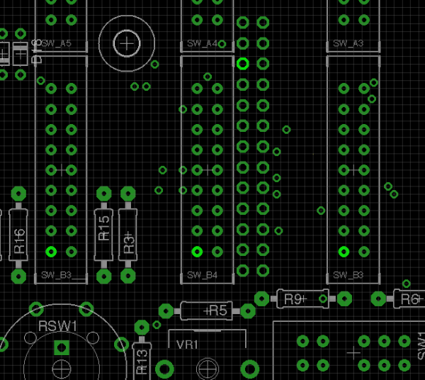
when the board is flipped over.
Sorry I havent had time to grab a pcb photo.
ryk |
|
|
Back to top
|
|
|
hautlle
Joined: May 23, 2011
Posts: 11
Location: KS
|
| Posted: Mon Jun 08, 2020 2:49 pm Post subject:
|
|
|
| ryktnk wrote: | | hautlle wrote: |
Sorry, I didn't use the correct terminology. The switch that gets no response is the Stage 2 Stage Count Control switch. The Gate Mode switch behaves as expected. |
Hello
No worries.
The diode to look at is D22, please check as previously described.
If the readings are 4.9-5v then please check carefully the soldering of
SW-A6 [ the Stage 2 Count control ]. Especially the bottom right corner pin
when the board is flipped over.
Sorry I havent had time to grab a pcb photo.
ryk |
I am only getting 4.55v out of D22. |
|
|
Back to top
|
|
|
ryktnk
Joined: Apr 24, 2008
Posts: 285
Location: london
Audio files: 1
|
| Posted: Tue Jun 09, 2020 2:26 am Post subject:
|
|
|
| hautlle wrote: | | ryktnk wrote: | | hautlle wrote: |
Sorry, I didn't use the correct terminology. The switch that gets no response is the Stage 2 Stage Count Control switch. The Gate Mode switch behaves as expected. |
Hello
No worries.
The diode to look at is D22, please check as previously described.
If the readings are 4.9-5v then please check carefully the soldering of
SW-A6 [ the Stage 2 Count control ]. Especially the bottom right corner pin
when the board is flipped over.
Sorry I havent had time to grab a pcb photo.
ryk |
I am only getting 4.55v out of D22. |
Hello
That is fine [ the diode has quite a voltage drop ]
The problem would now appear to be with the switch A6, please check carefully the pin soldering.
ryk |
|
|
Back to top
|
|
|
hautlle
Joined: May 23, 2011
Posts: 11
Location: KS
|
| Posted: Tue Jun 09, 2020 10:52 am Post subject:
|
|
|
| ryktnk wrote: | | hautlle wrote: | | ryktnk wrote: | | hautlle wrote: |
Sorry, I didn't use the correct terminology. The switch that gets no response is the Stage 2 Stage Count Control switch. The Gate Mode switch behaves as expected. |
Hello
No worries.
The diode to look at is D22, please check as previously described.
If the readings are 4.9-5v then please check carefully the soldering of
SW-A6 [ the Stage 2 Count control ]. Especially the bottom right corner pin
when the board is flipped over.
Sorry I havent had time to grab a pcb photo.
ryk |
I am only getting 4.55v out of D22. |
Hello
That is fine [ the diode has quite a voltage drop ]
The problem would now appear to be with the switch A6, please check carefully the pin soldering.
ryk |
After removing most of the solder with a sucker and re-soldering the switch I still had the same issue.
After inspecting all parts of the switch for a while I noticed there was a tiny spot of something splattered on the track inside the switch. I gently removed it with a toothpick and all is working now 

Thanks for your time and the wonderful module Ryk. I look forward to exploring the M185[/img]
Last edited by hautlle on Fri Jun 12, 2020 4:00 pm; edited 1 time in total |
|
|
Back to top
|
|
|
Still Sound
Joined: Jun 09, 2020
Posts: 1
Location: Canada
|
| Posted: Tue Jun 09, 2020 10:34 pm Post subject:
|
|
|
Hey guys,
Just finished my build, and it fires up for the test as it should, but it only seems to be 5 stages.
LEDs pingpong left to right 4 times, but only 5 LEDs.
Max stage switch also only lights 5 LEDs.
EDIT:
When running a normal sequence, it appears to be running through all 8 stages, but no LED indication on 6, 7, and 8.
Any help would be appreciated.
Thanks! |
|
|
Back to top
|
|
|
nativeVS
Joined: Dec 12, 2017
Posts: 14
Location: London
|
| Posted: Wed Jun 10, 2020 10:11 am Post subject:
|
|
|
Hi Ryk,
So, after resolving the previous issue I've now managed to calibrate CV1 & CV2 without issues, however I don't get any response from the Gate mode switches in the test mode (i.e. all stuck in top position). |
|
|
Back to top
|
|
|
ryktnk
Joined: Apr 24, 2008
Posts: 285
Location: london
Audio files: 1
|
| Posted: Wed Jun 10, 2020 11:48 am Post subject:
|
|
|
| Still Sound wrote: | Hey guys,
Just finished my build, and it fires up for the test as it should, but it only seems to be 5 stages.
LEDs pingpong left to right 4 times, but only 5 LEDs.
Max stage switch also only lights 5 LEDs.
EDIT:
When running a normal sequence, it appears to be running through all 8 stages, but no LED indication on 6, 7, and 8.
Any help would be appreciated.
Thanks! |
If you are having problems with some LEDs not lighting, it is a good idea to measure voltage on the LED drivers on the Main PCB.
Boot up the sequencer normally, turn off the clock, and use the NXT PRV blue buttons to select a stage.
Then measure the voltage between Pin 16, and the relevant pin on the LED Driver IC. [ see list below ]
Use the red probe on Pin16, and the black probe for the LED driver Pins.
You should see 1.8v on a correctly functioning pin that is active for that stage.
Here are the Pins to measure voltages on.
IC5 RED LEDs
Stage 1 - Pin 5
Stage 2 - Pin 6
Stage 3 - Pin 7
Stage 4 - Pin 8
Stage 5 - Pin 9
Stage 6 - Pin 10
Stage 7 - Pin 11
Stage 8 - Pin 12
IC6 GREEN LEDs
Stage 1 - Pin 5
Stage 2 - Pin 6
Stage 3 - Pin 7
Stage 4 - Pin 8
Stage 5 - Pin 9
Stage 6 - Pin 10
Stage 7 - Pin 11
Stage 8 - Pin 12
If all these volatges seem ok, then perform the same voltage tests, but
this time measuring the voltage on the LED directly on the PCB.
Red probe centre leg.
Green LED black probe on LHS leg
Red LED black probe on RHS leg.
Again if correct the voltage should be apprx 1.8v
If you are not seeing these voltage on the LEDs, there is most likely
a problem with the pin header soldering.
ryk |
|
|
Back to top
|
|
|
ryktnk
Joined: Apr 24, 2008
Posts: 285
Location: london
Audio files: 1
|
|
|
Back to top
|
|
|
nativeVS
Joined: Dec 12, 2017
Posts: 14
Location: London
|
| Posted: Wed Jun 10, 2020 1:51 pm Post subject:
|
|
|
Hi Ryk,
continuity is fine through to the pin of the processor, which only outputs about .1V  Well, at least it's in a socket. Well, at least it's in a socket.
Robert |
|
|
Back to top
|
|
|
ryktnk
Joined: Apr 24, 2008
Posts: 285
Location: london
Audio files: 1
|
| Posted: Fri Jun 12, 2020 11:34 am Post subject:
|
|
|
| nativeVS wrote: | Hi Ryk,
continuity is fine through to the pin of the processor, which only outputs about .1V Well, at least it's in a socket.
Robert |
Hello
Can you turn on the sequencer.
Stop the clock.
Select a stage with the NXT PRV buttons, and measure the voltage on the pin from the previous post, whilst adjusting the Gate Mode switch.
PS this is voltage that is sent to the processor for Gate Modes.
When you were using calibration test mode, did the Pots and Stage Count switches test ok.
ryk |
|
|
Back to top
|
|
|
|

 Forum index » DIY Hardware and Software