| Author |
Message |
sneakthief

Joined: Jul 24, 2006
Posts: 569
Location: Berlin
|
 Posted: Mon Feb 21, 2011 1:36 am Post subject: Posted: Mon Feb 21, 2011 1:36 am Post subject:
|
  |
|
5 good octaves is a reasonable goal for this vco. How many cents off are you on the 5th and 6th octaves? If you can get within 20 cents over that amount that's acceptable.
Re. 150k vs. 1.5m - these are Laurie's notes regarding his changes to the ASM-1 vco:
"R115 in some schematics has a value of 1M5 and a value of 150K in others. Changing this value adjusts the resting frequency of the VCO with a 0V control input. We currently use a 1M5 resistor which sets the initial VCO frequency to approximately 909Hz."
http://www.elby-designs.com/asm-1/documents/asm1-manual.pdf
ps. Is your 10v reference voltage OK?
_________________
Sneak-Thief - raw electrofunk |
|
|
Back to top
|
|
 |
moogasm
Joined: Dec 29, 2009
Posts: 13
Location: San Diego
|
| Posted: Tue Feb 22, 2011 10:15 am Post subject:
|
|
|
Thanks for the reply. I added a trim adjustment to the +-10V reference so it is dead on.
I made an interesting discovery. When I shorted out the 1.2M Iref resistor and dialed down the 500K pot to 150K the v/oct tracking is almost perfect out to 5 octaves. At 6 octaves the oscillator actually goes sharp 10-20 cents. There must have been a reason for the value change (1.5M to 150K). Perhaps the VCO tracks better with a higher Iref? I am going to go through the Magnus circuit description to see if I can figure it out. If anyone can explain this relationship I will be most appreciative.
Thanks,
Mike |
|
|
Back to top
|
|
|
frijitz
Joined: May 04, 2007
Posts: 1734
Location: NM USA
Audio files: 54
|
| Posted: Tue Feb 22, 2011 2:37 pm Post subject:
|
|
|
| tihsmud wrote: | | If anyone can explain this relationship I will be most appreciative. |
This basic design can easily track over 10 Octaves. The version on my website is within 0.1% up to 28 kHz.
Since there is no adjustable high-frequency tracking in the ASM design, you might want to try different values for R112. The value of 680R is for a different switching FET and a different converter pair. You also need to be sure the FET completely discharges C104. If not, C111 should be increased a bit.
One common cause of overtracking I discovered many years ago is spurious high-frequency oscillations in the expo converter. This is something that might change with different standing currents. Use a good high-impedance scope probe to look at the output of U100C. Use AC coupling and turn up the scope's gain, and have the VCO's frequency set at the top end.
In my design, I use two separate HF tracking compensation circuits. The value of R19 (reset correction) is much smaller (~100R). Then D1, R16 and R17 are added. These may not be needed for the MAT02 transistors, which have excellent log conformance.
You might want to try replacing U100 with a better device. Unfortunately, since it is a quad, there aren't all that many good options. I would suggest the OP482.
Oh, and definitely get rid of R138. It is not needed with modern opamps. Just short it out.
That should get you started.

Ian
edit: corrected U101 to U100
Last edited by frijitz on Fri Feb 25, 2011 10:53 pm; edited 1 time in total |
|
|
Back to top
|
|
|
Ricko
Joined: Dec 25, 2007
Posts: 251
Location: Sydney, Australia
Audio files: 27
|
| Posted: Fri Feb 25, 2011 10:37 pm Post subject:
|
|
|
Just to clarify, when Ian says R19 (& D1, R16, R17) he is referring to his circuit at
http://home.comcast.net/~ijfritz/sy_cir2.htm. This is the equiv of R112 in the ASM-2 circuits.
But I am confused about the numbers. In the ASM-2, there is U100-C etc. But U101 is the CA3140 so I don't think iit s a quad.
Is this right? For better specs in an ASM-2 or similar ENS76 opt 1 VCO try:
Upgrade TL074 to OP482
Upgrade CA3140 to eg OPA132
Upgrade J108 to J112
(Upgrade LM311 to LM319: not chip compatible)
If the high frequencies are going sharp, consider increasing R112, if they are going flat consider decreasing it.
Also, I noticed on the net a variant which had a diode from 0v to the CCO sawtooth output. Sorry URL lost. Anyone have any idea what the point of this might be: what would it be clipping? |
|
|
Back to top
|
|
|
frijitz
Joined: May 04, 2007
Posts: 1734
Location: NM USA
Audio files: 54
|
| Posted: Fri Feb 25, 2011 11:09 pm Post subject:
|
|
|
| Ricko wrote: | | But I am confused about the numbers. In the ASM-2, there is U100-C etc. But U101 is the CA3140 so I don't think iit s a quad. |
Thanks! I edited the post to correct that.
| Quote: | | If the high frequencies are going sharp, consider increasing R112, if they are going flat consider decreasing it. |
Let's think about that some more. His curve is going sharp with one standing current and flat with the other. However, the current through the integrating cap is the same in both cases. So it seems to me that the problem with the tuning curve is earlier in the circuit. That's why I suggested using better opamps (to reduce offsets) and checking for HF oscillations.
| Quote: | | Also, I noticed on the net a variant which had a diode from 0v to the CCO sawtooth output. Sorry URL lost. Anyone have any idea what the point of this might be: what would it be clipping? |
Possibly clipping a negative-going switching transient. (Note the CA3040 version does the same thing, since it is powered at V- = 0.) If it is a reallly short transient, then a TL07x, etc. buffer will get rid of most of it. On the version at my website that's what the LF351 and 8 pF cap do. If it is really strong I would prefer to find where the speeds of the components are not matching up and trying to fix it from that angle.
Ian |
|
|
Back to top
|
|
|
mrdave45

Joined: Oct 05, 2014
Posts: 5
Location: Maidstone UK
|
Posted: Sun Oct 05, 2014 6:43 am Post subject:
ASM2 Cougar
Subject description: new build and looking for a few answers.... |
|
|
Hey all, Have joined this forum after following link from elbys site.
I have just received my asm2 cougar full kit and there are a few things that dont make too much sense. Maybe theres still a few typos (even on the front panel, not sure, thats why Im here).
So my first question is......
Has anybody built an ASM 2 Cougar?
Im also curious to what documentation other people received with their kits. Some talk of CDs and large printed overlays of pcbs etc.
Although Ive managed to find a lot of the things I need on the elby website I still seem to be missing a few bits of info.
The kit came with
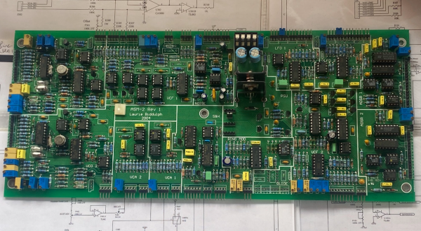
asm2 pcb v2. Found schematics and bom. Think I should be ok with this...
cgs36m pulse divider pcb. Found overlay online and schematics, I think i should also be ok with this although I think quite a few of the features arent being used with the cougar panel. (Maybe thats what i can use some of the unlabled connections for).
some kind of psu pcb. Advertised as monodual but i dont think its one of those. On the board it says DC/DC Power unit v0.3 but i cant find a schematic or bom to fit this.
MonoDAC (this hasnt arrived yet, I guess theyre getting more made up) I have a printout of the overlay but i cant find schematics or anything about this. Anyone?
There also seems to be a few unlabled sockets on the cougar panel. Is that just so i can decide on minor mods?
The vco inputs seem to be a little wierd. There are 3 lin cv in puts on the panel but only 2 on the pcb. Do think its intended that i stick another 100k resistor on the bus connecting all the inputs to the inverting input of the opamp and hack it together?
Same with the initial pwm (the genie block diagram has been useful here) sent to the 100k pwm 1, and use the same trick as above into pwm 2 input but using 300k resistors for the pwm 1 and pwm 2 knobs.
Anyway, I think this is plenty for now. I still have lots of questions, some rather basic Im afraid.
btw, Do you think its worth starting a new topic just for asm 2 cougar builds? Maybe not enough get sold huh? Ive found very limited info on these synths online
Many thanks in advance.
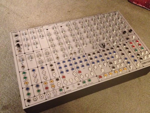
| Description: |
| ASM 2 Cougar control panel mostly assembled front angle |
|
| Filesize: |
132.76 KB |
| Viewed: |
513 Time(s) |
| This image has been reduced to fit the page. Click on it to enlarge. |
|
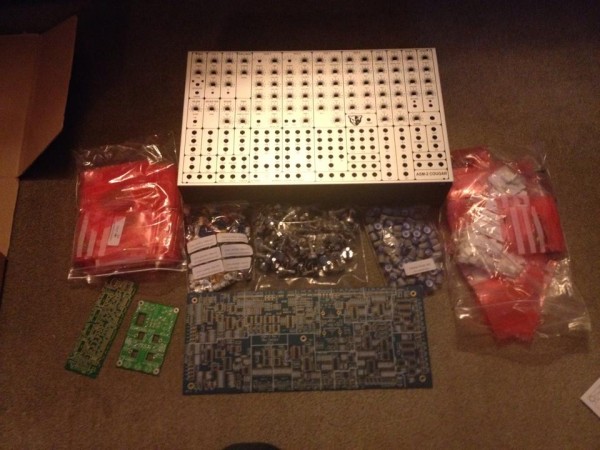
| Description: |
| Over view of ASM 2 Cougar full kit. |
|
| Filesize: |
90.87 KB |
| Viewed: |
502 Time(s) |
| This image has been reduced to fit the page. Click on it to enlarge. |
|
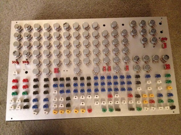
| Description: |
| Rear of ASM 2 Cougar control panel. |
|
| Filesize: |
107.99 KB |
| Viewed: |
439 Time(s) |
| This image has been reduced to fit the page. Click on it to enlarge. |
|
|
|
|
Back to top
|
|
|
mrdave45
Joined: Oct 05, 2014
Posts: 5
Location: Maidstone UK
|
| Posted: Sun Oct 05, 2014 6:49 am Post subject:
|
|
|
| BTW, I forgot to mention, I am totally blown away by the things that you guys have been constructing. Hopefully I won't appear too tedius! I have only built one synth (a transcendant 2000 kit i picked up about 3 years ago) and that was really quite straight forward in comparison to this! |
|
|
Back to top
|
|
|
Cnicht
Joined: Oct 26, 2014
Posts: 4
Location: Uk
|
| Posted: Sun Oct 26, 2014 12:16 pm Post subject:
|
|
|
This is my first post on here so please be gentle!
I'm just assembling and testing the ASM2 after having the PCB for some time and having problems with the oscillator sync. Having done some probing on the board it seems that U105, the sync summer op amp doesn't have connection to +/- 15V - there are no tracks on the board! I added some wire links to the supply rails but the op amp just got hot!
Has anyone else had this problem and invented fixes?
Many thanks. |
|
|
Back to top
|
|
|
mrdave45
Joined: Oct 05, 2014
Posts: 5
Location: Maidstone UK
|
| Posted: Sun Oct 26, 2014 1:24 pm Post subject:
|
|
|
| Hi, I've got a rev 2 board. Have just checked u105, pin 4 is connected to -15, pin 7 is connected to +15. I haven't got as far as testing the sync yet but I do seem to have connections at least. |
|
|
Back to top
|
|
|
Cnicht
Joined: Oct 26, 2014
Posts: 4
Location: Uk
|
| Posted: Sun Oct 26, 2014 1:28 pm Post subject:
|
|
|
| I seem to have a Rev 1 board dated 2004 - maybe this problem was corrected on later revisions? |
|
|
Back to top
|
|
|
Cnicht
Joined: Oct 26, 2014
Posts: 4
Location: Uk
|
| Posted: Mon Oct 27, 2014 3:00 am Post subject:
|
|
|
I contacted Elby Designs who confirmed that there are missing supply tracks from this board revision. I've added these links and sync now works.
There are also some other changes needed on this board revision too. |
|
|
Back to top
|
|
|
sneakthief
Joined: Jul 24, 2006
Posts: 569
Location: Berlin
|
|
|
Back to top
|
|
|
Cnicht
Joined: Oct 26, 2014
Posts: 4
Location: Uk
|
| Posted: Mon Oct 27, 2014 3:29 am Post subject:
|
|
|
Sample & Hold Module The footprint for Q901 in the Sample & Hold module is incorrect. For optimum performance it is recommend that you carefully remove Q901 and rotate it through 180° as shown in the component overlay supplied with your pcb.
Noise Module There is a problem with the Coloured Noise section of the Noise Module which results in a large in-balance in output levels between the Red and Blue outputs. The following modification has been found to improve the situation:1. Replace U602 (TL082) with an MC1458 2. Insert a series resistor of approximately 12K between P602 and C604. This is best done by inserting the resistor in the wire to the CW terminal of P602
10V Reference Circuit The ASM-2 PCB does not provide tap-off points for the 10V Reference Circuit. You will normally need to use these when adding a FINE TUNE and COARSE TUNE pot to the VCO. The best point to access these rails is by soldering wires to the two outer legs of trimpots P100 and/or P150. I have also found that there is enough variation in the tolerance of the circuit components that may result in the output not sitting at 10V. If this is the case then you should adjust the value of R3 and/or R6 as required. Future releases of this pcb will incorporate a 500R trimpot in series with each of these resistors and the values of R3 and R6 lowered to 820R. This will allow fine tuning of the reference voltages.
Hope this helps! |
|
|
Back to top
|
|
|
sneakthief
Joined: Jul 24, 2006
Posts: 569
Location: Berlin
|
| Posted: Mon Oct 27, 2014 9:36 am Post subject:
|
|
|
Many thanks!
I had already tapped the 10V for the Octave Switcher PCB add-on. Not sure about ever having problems with my S&H. As for the noise colour, that never seemed to bother me.
I use my ASM-2 weekly for almost 10 years now
_________________
Sneak-Thief - raw electrofunk |
|
|
Back to top
|
|
|
nedo
Joined: Aug 02, 2016
Posts: 1
Location: nowhere
|
| Posted: Wed Aug 03, 2016 12:20 am Post subject:
|
|
|
Hi guys nice to meet you!
I'm currently calibrating an Asm2 cougar.
All good with VCO1 but VCO2 is acting strange..
When I apply +5V to a VCO2 log input, it jumps around 47 kHz instead of 28kHz.
I tried to turn the V/Octave trimpot but it's almost ineffective and at this frequency the saw is a bit distorted an a smaller in amplitude (this only when I remove the jumper LK150 to disconnect the init freq. pot).
I suspect a faulty FET, or maybe the unbranded LM394 elby sent is not working well.
I already tried to swap CA3140 and TL074 between the 2 oscillators but nothing changes at all..
I check all resistors values in the tracking section but they seem corrects (ofc I'll keep on searching).
Anyone as already gone through this problem?
I hope to hear you back, all the best guys! |
|
|
Back to top
|
|
|
djsoulfeggio
Joined: Sep 10, 2022
Posts: 1
Location: Mesa, AZ
|
|
|
Back to top
|
|
|
Dragon's Lair

Joined: Dec 29, 2006
Posts: 205
Location: Hope BC, Canada
Audio files: 1
|
|
|
Back to top
|
|
|
|

 Forum index » DIY Hardware and Software