| Author |
Message |
loss1234

Joined: Jul 24, 2007
Posts: 1536
Location: nyc
Audio files: 41
|
|
|
Back to top
|
|
 |
fluxmonkey
Joined: Jun 24, 2005
Posts: 708
Location: cleve
|
 Posted: Wed Nov 12, 2008 8:13 am Post subject: Posted: Wed Nov 12, 2008 8:13 am Post subject:
|
  |
|
| loss1234 wrote: | strange update
i tried it with a +/- 12 volt (not 15 volt psu as is required) and the LFO sounds were almost entirely gone!! i am wondering if the other PSU just couldnt give a clean voltage?
any guesses?
this just might work itself out
thanks |
were the 2 different supplies of the same amperage? praps the 15v supply is too small.
did you try the advice you got on other lists, regarding grounding? running separate grounds to each section in a "star" config using heavier wire?
b
_________________
www.fluxmonkey.com |
|
|
Back to top
|
|
|
sneakthief

Joined: Jul 24, 2006
Posts: 569
Location: Berlin
|
| Posted: Wed Nov 12, 2008 8:33 am Post subject:
|
|
|
i have no lfo bleed-through whatsoever.
i don't understand what you've done here - are you bypassing the internal psu?
from the ASM-2 PSU schematics:
| Quote: |
If using an external well regulated DC power supply (+/-15VDC @ 200mA) then you may omit U1,
You should then fit a wire link in positions D1 and D2.
|
to be honest, i think you're better off *not* using the power one psu and just get a simple dual-rail power supply (24-0-24DC @ 300mA ) to feed the onboard psu. this is a totally inexpensive thing to cook up. just follow elby's "raw-DC" psu schematics.
that way you can save the power one psu for other modular projects.
as for me, i'm using a gigantic obscure PSU rack that i got from ebay. i changed this monster 3amp psu's onboard regulators to +/-20V and that powers my ASM-2 as well as several other racks.
the key was that each rack had it's own 7915/7815 regulator pair so that they would be isolated from each other and reduce interference.
_________________
Sneak-Thief - raw electrofunk |
|
|
Back to top
|
|
|
loss1234
Joined: Jul 24, 2007
Posts: 1536
Location: nyc
Audio files: 41
|
|
|
Back to top
|
|
|
loss1234
Joined: Jul 24, 2007
Posts: 1536
Location: nyc
Audio files: 41
|
|
|
Back to top
|
|
|
Uncle Krunkus
Moderator

Joined: Jul 11, 2005
Posts: 4761
Location: Sydney, Australia
Audio files: 52
G2 patch files: 1
|
| Posted: Sat Jun 06, 2009 5:32 pm Post subject:
|
|
|
Just a quick note here to say that after a lot of thought, I've decided that if I had the chance to do it all over again, I would not use the front panel, semi-patched out version which I documented in this thread.
This is specifically because I have enjoyed building other Synth DIY modules, and have found that only having partial control of input/output connection options has actually hindered my ability to get the most out of this synth.
However, if this was the only DIY analogue synth module in your kit then the layout as documented may be just right.
I think the best option, (and one which I may yet convert it to!   ) is a "no switch", controls and attenuators only, main layout, with a connection matrix (like the VCS Synthi) and a bank of 8->? generic in/out sockets. ) is a "no switch", controls and attenuators only, main layout, with a connection matrix (like the VCS Synthi) and a bank of 8->? generic in/out sockets.
If anyone wants anymore details of how I think this could be implememented, just ask.
I don't mean to be a wet blanket for anyone who has gone a different way. I just wanted to share some hard earned experience.
_________________
What makes a space ours, is what we put there, and what we do there. |
|
|
Back to top
|
|
|
loss1234
Joined: Jul 24, 2007
Posts: 1536
Location: nyc
Audio files: 41
|
|
|
Back to top
|
|
|
Uncle Krunkus
Moderator
Joined: Jul 11, 2005
Posts: 4761
Location: Sydney, Australia
Audio files: 52
G2 patch files: 1
|
| Posted: Sat Jun 06, 2009 8:44 pm Post subject:
|
|
|
I'd use 3.5mm box type sockets. The switching mono type ones. Mainly cos I've already built up a collection of about 70 of them. I'd bus solder them into a slab and back them with a piece of stripboard. That way, you don't even need the nuts and washers on the front. I'd have them normaled along input rows, so you could have multiple outs but only one input per summing resistor. Using 3.5mm plugs as patch pins would enable cords for extra ins and outs. You can also use different plugs/pins as AC or DC coupling and as rectifiers.
These box type sockets are cheap and nasty, but they're also easy to replace if they fail.
_________________
What makes a space ours, is what we put there, and what we do there. |
|
|
Back to top
|
|
|
Uncle Krunkus
Moderator
Joined: Jul 11, 2005
Posts: 4761
Location: Sydney, Australia
Audio files: 52
G2 patch files: 1
|
| Posted: Sat Jun 06, 2009 9:08 pm Post subject:
|
|
|
Okay,
Maybe I should re-think all that.
I just had a quick look, and there's 54 possible inputs and 31 possible outputs! 
That would mean a matrix made up of 1674 sockets! And using those sockets, the matrix would be as big as the whole front panel is now! 
Well,
Probably heaps of those connection options are invalid or redundant. So I still think the basic idea is sound.
I'm gonna look into it a deeper and see what I can see.
I need to have a look at the patch matrix from the VCS and get an idea of what's important and what's not. Anyone got a clear pic of it?
_________________
What makes a space ours, is what we put there, and what we do there. |
|
|
Back to top
|
|
|
sneakthief
Joined: Jul 24, 2006
Posts: 569
Location: Berlin
|
| Posted: Sun Jun 07, 2009 8:40 am Post subject:
|
|
|
My experience has been a little bit different. I chose to use as many of the inputs and outputs as possible within the space I had for each "module". It's been pretty satisfying so far.
I really like having the pots near their respective jacks. As attractive as the Wiard modules are, I don't think I like having the jacks lumped together in one section because I end up having to hunt around too much so I can figure out what the corresponding knob is. YMMV.
_________________
Sneak-Thief - raw electrofunk |
|
|
Back to top
|
|
|
crochambeau

Joined: May 18, 2008
Posts: 31
Location: earth.
|
| Posted: Sun Jun 07, 2009 9:08 am Post subject:
|
|
|
| sneakthief wrote: | | I really like having the pots near their respective jacks. |
This is the slant I'm taking as well. Pictured is my mock up of a 4u 19" panel housing one VCO, ADSR, LFO and VCA. I'm going with banana normalized with DPDT and LED indication for banana. Final build will be 13u plus one for power switch, indicators and output taps on some raw patina'd aluminum stock.
 |
|
|
Back to top
|
|
|
Uncle Krunkus
Moderator
Joined: Jul 11, 2005
Posts: 4761
Location: Sydney, Australia
Audio files: 52
G2 patch files: 1
|
| Posted: Sun Jun 07, 2009 4:09 pm Post subject:
|
|
|
| sneakthief wrote: | | As attractive as the Wiard modules are, I don't think I like having the jacks lumped together in one section because I end up having to hunt around too much so I can figure out what the corresponding knob is. |
Yeah, that's a valid point. I just thought it would be nice keep with the "hardly any cables at all" idea while expanding the options. But, to be honest, I don't actually use my analogue gear enough to justify "re-building" the main component. But maybe I don't use it 'cos of the way it's built? I don't know. I'm so confused these days about why I do SDIY in the first place. Maybe I should go back to model making for a while. 
Anyway, I did find a good option for the matrix.
2*40 way headers, (one for each output), say 30 of them. Stacked up on a piece of perf board. Instead of patch pins, use tagged header shunts. They're like the links which choose the master/slave option on the back of a hard-drive, except they have a little handle on the back.
Of course you lose the "normaled" option, but the AC/DC coupling and the rectifier idea are probably still feasible.
I've been mulling over upgrading my SoundLab to the SoundLab Ultimate, so maybe it would be worth incorporating this matrix idea into a smaller unit like that?
I can't really say that I've exhausted the possibilities of the Sorcerer panel, as I still have 16 sockets unconnected!
_________________
What makes a space ours, is what we put there, and what we do there. |
|
|
Back to top
|
|
|
Uncle Krunkus
Moderator
Joined: Jul 11, 2005
Posts: 4761
Location: Sydney, Australia
Audio files: 52
G2 patch files: 1
|
|
|
Back to top
|
|
|
chriswilliams

Joined: May 17, 2005
Posts: 17
Location: Perth, Western Australia
|
|
|
Back to top
|
|
|
Uncle Krunkus
Moderator
Joined: Jul 11, 2005
Posts: 4761
Location: Sydney, Australia
Audio files: 52
G2 patch files: 1
|
|
|
Back to top
|
|
|
chriswilliams
Joined: May 17, 2005
Posts: 17
Location: Perth, Western Australia
|
| Posted: Tue Jul 07, 2009 8:59 am Post subject:
|
|
|
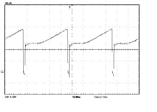
Got the VCO's sorted !!
Turns out the JFETs were at fault - I replaced them with J111's I had sitting in an unused project and all is well - oscillating at an (now audible) 880Hz 
These J111's were Fairchild branded , whereas the J108's I had were from Futurlec and without an obvious manufacturer. A warning to others perhaps? 
Quite annoying, but I guess in the whole process of debugging this circuit I now understand he VCO design!
Thanks Uncle Krunkus for the PDFs - I think Laurie has updated them again on his website since - I think very minor changes though |
|
|
Back to top
|
|
|
Sine

Joined: Sep 10, 2007
Posts: 111
Location: Netherlands
|
|
|
Back to top
|
|
|
Skrog Productions

Joined: Jan 07, 2009
Posts: 1225
Location: Scottish Borders
Audio files: 160
|
| Posted: Fri Jul 17, 2009 8:34 am Post subject:
|
|
|
Hello ASM builders, I've had my bare board sitting around for 6 months now and i'm itching to get stuck into it, but i've been thinking of sorting out all possible mods i might do beforehand.
Will be mostly used for melody / bass / lead sounds.
One idea is to have a 5 or 6 Oscillator ASM2 in semi modular form, but im wondering if it would be easier to get a super thick sound using simple wave folders (cgs) and sub osc's/ frequ. dividers to enhance the original 2 vco's (8+ audio input mixer for each vcf).
Using a switch to select vcf's in parallel or series (with input/output gain control) and a another switch to lock both vcfs to vcf 1 c.v. bus.
If i were to go for 5 osc's would i need to buffer the one incoming c.v. from my ELBY poly-dac , almost like an internally wired 1 to 5 multiple as on my modular system ???.
Seeing all these fantastic ASM 2 creations so far is inspiring.
Cheers
David W |
|
|
Back to top
|
|
|
State Machine
Janitor


Joined: Apr 17, 2006
Posts: 2810
Location: New York
Audio files: 24
|
| Posted: Fri Jul 17, 2009 9:36 am Post subject:
|
|
|
| Quote: | | Turns out the JFETs were at fault - I replaced them with J111's I had sitting in an unused project and all is well - oscillating at an (now audible) 880Hz Smile |
Good news, I saw your oscillograph and was interested what the outcome would be.
| Quote: | | These J111's were Fairchild branded , whereas the J108's I had were from Futurlec and without an obvious manufacturer. A warning to others perhaps? Confused |
Good warning. Something to be aware of when purchasing components. When selling components for the Klee sequencer, it turned out I had a mess of shift register chips that I sold and ended up bad. They were some obscure brand of chip from India and they were manufactured back in like 1984 or something. I replaced many in the field and used all Motorola or TI chips without any more incidents.
Names to trust you ask (not complete of course and just my opinion):
Just analogs, not digital:
Motorola
TI
National Semi
Maxium
Fairchild
OKI
JRC
Micrel
IRC (IRF series Trannies)
Harris
Linear Technology .... Just to name a few .....
| Quote: | | Quite annoying, but I guess in the whole process of debugging this circuit I now understand he VCO design! |
Probing around and debugging is the best teacher. I agree. Ijust went through a session of debugging a pile of "C" code but got things sorted out.  Yes, so annoying when you want to get a project done BUT when you have to debug and you get it working, then the satisfaction factor is increased ten fold .... Good work !!! Yes, so annoying when you want to get a project done BUT when you have to debug and you get it working, then the satisfaction factor is increased ten fold .... Good work !!!
Bill |
|
|
Back to top
|
|
|
sneakthief
Joined: Jul 24, 2006
Posts: 569
Location: Berlin
|
| Posted: Fri Jul 17, 2009 10:53 am Post subject:
|
|
|
| Skrog Productions wrote: | Hello ASM builders, I've had my bare board sitting around for 6 months now and i'm itching to get stuck into it, but i've been thinking of sorting out all possible mods i might do beforehand.
Will be mostly used for melody / bass / lead sounds.
One idea is to have a 5 or 6 Oscillator ASM2 in semi modular form, but im wondering if it would be easier to get a super thick sound using simple wave folders (cgs) and sub osc's/ frequ. dividers to enhance the original 2 vco's (8+ audio input mixer for each vcf).
Using a switch to select vcf's in parallel or series (with input/output gain control) and a another switch to lock both vcfs to vcf 1 c.v. bus.
If i were to go for 5 osc's would i need to buffer the one incoming c.v. from my ELBY poly-dac , almost like an internally wired 1 to 5 multiple as on my modular system ???.
|
1. re. 5 or 6 asm2 vco's - you don't really mean building 3 entire asm2's, do you? or were you considering building another 3 or 4 ken stone vco's? i can see how having an extra one of those would be handy, but bear with me as i discuss alternatives to any more than that.
2. if you're into a thick saw-wave sound, then look no further then the yusynth saw animator module: http://yusynth.net/Modular/EN/SAWANIM/index.html
3. i can't imagine a bank of 5 or 6 square waves is going to sound much better than a couple of asm2 vco's with their pwm inputs being modulated by lfo's
4. as for the triangle and sine waves, i don't know how much extra mileage you get from having a whole bunch of them simultaneously playing... does anyone else have thoughts about this? for me at least, the simple wave folder is more about distortion than thickening. that said, they can sound nice going through diode-based distortion. the blacet vc-wave output is a good example of this (it uses a white led for distortion). some like the sounds of a green led as a wave-rectifier too (serious!)
5. re. buffering - i guess this depends on how stable the polydac output is. i regularly drive 3 or 4 (unbuffered) vco's from single Midibox CV outputs without any problems. if you're concerned, you could simply make a buffer circuit using only two opamp chips, eg. a tl072 and a tl074. one of the opamp channels would be used to buffer the incoming cv signal and it would be split to the other 5 opamp channels. wiring this is dead simple: all of the respective inputs would go to the + of opamp the channels, while each - would be connected to it's corresponding output.
_________________
Sneak-Thief - raw electrofunk |
|
|
Back to top
|
|
|
Skrog Productions
Joined: Jan 07, 2009
Posts: 1225
Location: Scottish Borders
Audio files: 160
|
| Posted: Sat Jul 18, 2009 4:26 am Post subject:
|
|
|
Thanks Sneakthief.
I was initially thinking of cloning the vco section a few times to make a sort of real version of an old softsynth called the Pentagon i have .
I like the idea of the yusynth saw animator (I've built his triple clock divider for my 2 mfos sequencers) .
It's good to do most of this pondering first instead of half way thru a build as usual ha ha.
Re think....
ASM vco's on the board with a saw animator / wave folder / sub osc
added per vco.
Maybe just 1 mixer with 2 raw waves from each vco and 3 modifiers per vco ( 5 detuned against 5) into selectable vcf's.
Ok, i'll start doodling some block diagrams on scrap paper. |
|
|
Back to top
|
|
|
synthnl

Joined: Oct 19, 2007
Posts: 33
Location: Ede
|
|
|
Back to top
|
|
|
difficultdave
Joined: Jan 04, 2011
Posts: 1
Location: Sydney Australia
|
Posted: Tue Jan 04, 2011 6:43 am Post subject:
 asm-3? asm-3?
Subject description: news I got from elby_designs |
|
|
I emailed elby_designs@ozemail.com.au to see when the next batch of motherboards would be out and the reply was he has a few back-orders but is still finalizing the new layout with a sub-oscilator for each vco.
He promised it would be out soon. |
|
|
Back to top
|
|
|
Skrog Productions
Joined: Jan 07, 2009
Posts: 1225
Location: Scottish Borders
Audio files: 160
|
|
|
Back to top
|
|
|
moogasm
Joined: Dec 29, 2009
Posts: 13
Location: San Diego
|
| Posted: Mon Feb 21, 2011 12:53 am Post subject:
ASM-2 VCO Tracking |
|
|
This is my first post. I just finished my ASM-2 and following the calibration procedure in the ASM-2 manual the VCOs only track over 4-5 octaves in the low frequency range. A few questions:
What should my expectations be for the VCO tracking?
Is there an alternative procedure that might give better results?
Are there any modifications or part substitutions that can improve the VCO's v/oct performance?
Why did the ASM-2 use a 1.5M resistor in the current mirror as opposed to the ASM-1's 150K?
Does it make sense to add high frequency compensation to the design?
I have already changed the resistor value in sawtooth level shifter to get the sawtooth centered about +-5V.
I bought the MAT-02 and tempco from Laurie. I got the rest of the parts from Futurlec. Should I rebuy some of the critical parts from Mouser or Digikey just in case?
Thanks,
Mike |
|
|
Back to top
|
|
|
|

 Forum index » DIY Hardware and Software