| Author |
Message |
Uncle Krunkus
Moderator

Joined: Jul 11, 2005
Posts: 4761
Location: Sydney, Australia
Audio files: 52
G2 patch files: 1
|
 Posted: Thu Jul 27, 2006 3:06 pm Post subject: Posted: Thu Jul 27, 2006 3:06 pm Post subject:
|
  |
|
Thanks BigTex,
I know what you mean about having common mod type inputs next to each other. I was trying to break them up, thinking that, as they are just SPDT's, having different inputs paired together would decrease the similarity of function between the two. But I'm now wondering whether that is actually true. I've got a feeling that it's 6 to one, half a dozen to the other, if so, you're absolutely right. Unless I had the same inputs multipled to rotarys on every mod, there will always be some combinations which are inaccessable.
I'm gonna sit back and imagine actually setting up some sounds tonight.
_________________
What makes a space ours, is what we put there, and what we do there. |
|
|
Back to top
|
|
 |
bigtex

Joined: Mar 30, 2006
Posts: 323
Location: Cupertino, California
|
| Posted: Thu Jul 27, 2006 3:08 pm Post subject:
|
|
|
| Uncle Krunkus wrote: | | I'm gonna sit back and imagine actually setting up some sounds tonight. |
Yes. Like "air guitar" except with "air patch cables" (rocking out!).
 |
|
|
Back to top
|
|
|
Uncle Krunkus
Moderator
Joined: Jul 11, 2005
Posts: 4761
Location: Sydney, Australia
Audio files: 52
G2 patch files: 1
|
| Posted: Tue Aug 15, 2006 3:53 am Post subject:
Finalising the layout (help needed) |
|
|
Okay dudes, (and Dudettes)
I need some serious help now.
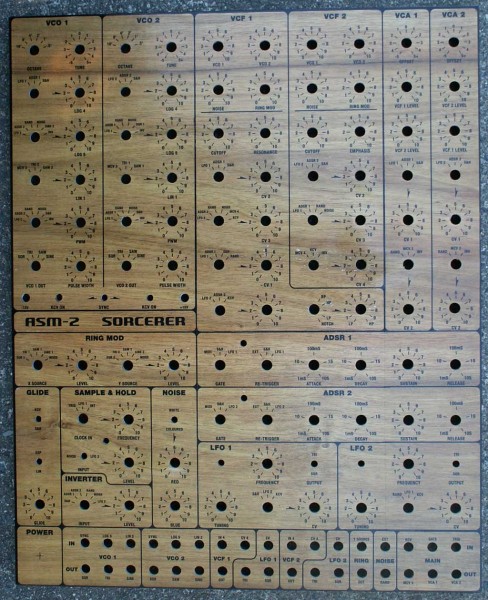
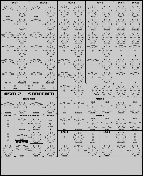
The layout is almost finished, but I need some sharp eyes to look it over and give me some specific feedback about connection options, etc. I'm particularly unsure about the gate and trigger options on the ADSRs.
I've included some of your previous ideas; -
Like similar mod option groupings, and noise mod options for the VCFs and RingMod, and LFO as a S&H input. In fact I've doubled the number of modulation options by incorporating more rotary switches (I had a stock of them anyway).
And any problems with the aesthetics of the layout as well.
As you can imagine, once I start drilling holes and mounting components, Murphy's law says that some things will need to change. I just want the list of unplanned modifications as short as possible.
Thanks in advance to anyone who has the time to help. 
PS Thanks for pointing out that Sorcerer only has 1 "c" in it!! Doh!@ 
| Description: |
|
| Filesize: |
202.7 KB |
| Viewed: |
695 Time(s) |
| This image has been reduced to fit the page. Click on it to enlarge. |
|
_________________
What makes a space ours, is what we put there, and what we do there. |
|
|
Back to top
|
|
|
zipzap
Joined: Nov 22, 2005
Posts: 559
Location: germany
Audio files: 24
|
| Posted: Tue Aug 15, 2006 10:24 am Post subject:
|
|
|
Just some thoughts: I would like some patching options and say 1 or 2 mixers with the option to rout them to your cvs. You´ve already covered most possibilities, but you never know. Those rotary switches might have a few more settings.
You´ve got octave and tune pots. If the tune-pot has to cover an whole octave it might not be finetunish enough.
For the lfos i would include a shape-controll. Never want to miss it!
And independant rise and fall lag can be very powerful and takes only another pot.
How are the vcfs and vcas connected? parallel/seriel?
The overall design looks really cool!
_________________
http://www.myspace.com/lorolocoacousticpop
http://www.myspace.com/petrolvendor
music and transcribed jazz basslines |
|
|
Back to top
|
|
|
Uncle Krunkus
Moderator
Joined: Jul 11, 2005
Posts: 4761
Location: Sydney, Australia
Audio files: 52
G2 patch files: 1
|
| Posted: Tue Aug 15, 2006 4:14 pm Post subject:
|
|
|
The section at the bottom will have normalised 6.5mm patch points, but I'm afraid I can't fit any more controls, (I've already got the sheet of aluminium, and at 430*530 I wouldn't want it any bigger.)
The octave switchers will have their own trimmers, referenced off the precision +/- 10V supply inside, so I don't think the fine tuning will be a problem.
What exactly do you mean by shape control, and rise fall lag? The PCB is finished, so I'm not really doing much more in the way of actual circuit function mods.
I'm going to have separate outputs for each VCA. They can be fed by mixed levels of either VCF, which in turn have a separate mix of the four sources.
_________________
What makes a space ours, is what we put there, and what we do there. |
|
|
Back to top
|
|
|
zipzap
Joined: Nov 22, 2005
Posts: 559
Location: germany
Audio files: 24
|
|
|
Back to top
|
|
|
Uncle Krunkus
Moderator
Joined: Jul 11, 2005
Posts: 4761
Location: Sydney, Australia
Audio files: 52
G2 patch files: 1
|
|
|
Back to top
|
|
|
questionable
Joined: Aug 27, 2006
Posts: 42
Location: southern california
|
| Posted: Tue Aug 29, 2006 12:39 pm Post subject:
|
|
|
| anyone have any audio file examples (i've already listened to sneakthief's "noodling")? |
|
|
Back to top
|
|
|
Uncle Krunkus
Moderator
Joined: Jul 11, 2005
Posts: 4761
Location: Sydney, Australia
Audio files: 52
G2 patch files: 1
|
| Posted: Wed Sep 06, 2006 7:17 pm Post subject:
|
|
|
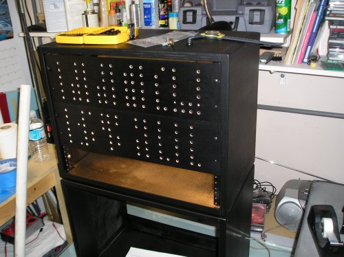
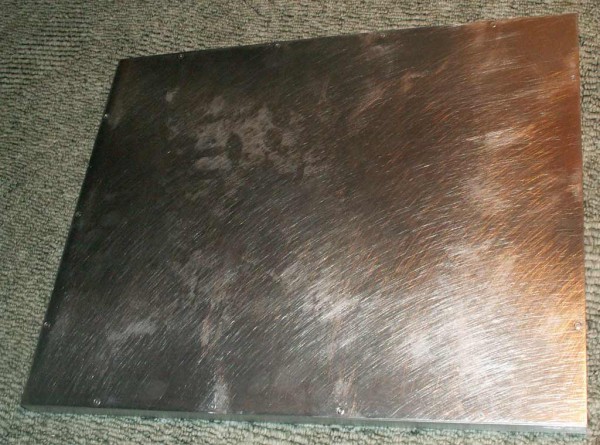
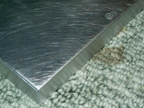
Here's the first three construction photos. Let me know if anyone finds these handy or inspirational.
| Description: |
| First up, I attached a 20*12mm L stock frame all around the 2mm front panel. This helps to stop any flexing in the panel, and gives me something to attach the rest of the case to. |
|
| Filesize: |
103.73 KB |
| Viewed: |
475 Time(s) |
| This image has been reduced to fit the page. Click on it to enlarge. |
|
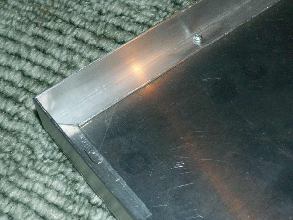
| Description: |
I decided to pop rivet the frame on, as the front will be covered in veneer and I didn't want any chance of things coming loose etc.
I had to countersink the rivet heads so they wouldn't cause lumps behind the veneer. |
|
| Filesize: |
83.22 KB |
| Viewed: |
519 Time(s) |
| This image has been reduced to fit the page. Click on it to enlarge. |
|
| Description: |
| Then I filed the rivet heads flat with the surrounding panel. The great thing about covering this in veneer is it actually helps if you scratch it up. |
|
| Filesize: |
113.08 KB |
| Viewed: |
528 Time(s) |
| This image has been reduced to fit the page. Click on it to enlarge. |
|
_________________
What makes a space ours, is what we put there, and what we do there. |
|
|
Back to top
|
|
|
Uncle Krunkus
Moderator
Joined: Jul 11, 2005
Posts: 4761
Location: Sydney, Australia
Audio files: 52
G2 patch files: 1
|
| Posted: Thu Sep 14, 2006 3:52 am Post subject:
|
|
|
Okay,
here's the next set of three pics.
Things are moving along really well.
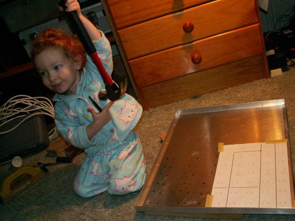
I printed off some reversed drilling guides and centre punched every hole from the inside.
I wanted to drill the locator holes first, as they only go through the aluminium. I always put pilot holes of 1.5mm (1/32) through first and then use wood drill bits (they have the outside edges raised with a spike in the middle) for any hole which you want centred and round! You can buy them from hardware stores, but you can make your own out of a standard bit, if you have some kind of grinding wheel, and a bit of practice.
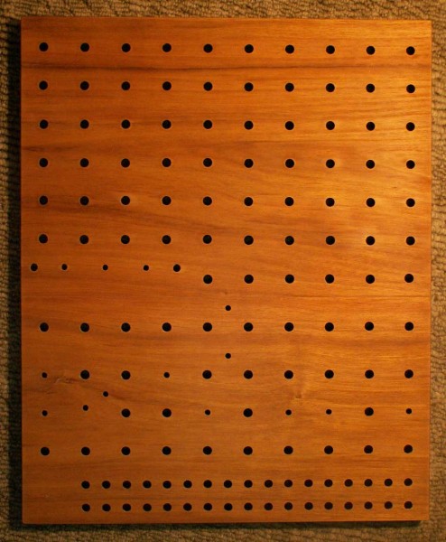
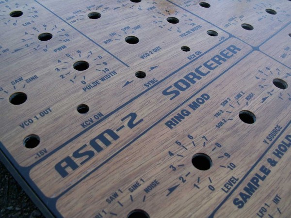
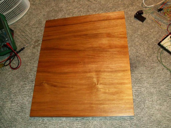
With all the locator holes drilled and cleaned, I wiped over with some isopropyl alchohol and ironed on the veneer sheets. After filling the grain and sanding smooth, I gave it a coat of satin enamel. Next morning I decided it was too thick and wiped it off with turpentine and an open weave cloth. It actually ended up being a really beautiful finish. Now to drill the real holes!
| Description: |
| Here, my beautiful assistant shows how easy it is to swing a hammer! |
|
| Filesize: |
62.82 KB |
| Viewed: |
407 Time(s) |
| This image has been reduced to fit the page. Click on it to enlarge. |
|
| Description: |
| Locator holes drilled, time to iron on the veneer. |
|
| Filesize: |
92.87 KB |
| Viewed: |
459 Time(s) |
| This image has been reduced to fit the page. Click on it to enlarge. |

|
| Description: |
| Finished panel ready for real holes. |
|
| Filesize: |
104.36 KB |
| Viewed: |
470 Time(s) |
| This image has been reduced to fit the page. Click on it to enlarge. |
|
_________________
What makes a space ours, is what we put there, and what we do there. |
|
|
Back to top
|
|
|
Uncle Krunkus
Moderator
Joined: Jul 11, 2005
Posts: 4761
Location: Sydney, Australia
Audio files: 52
G2 patch files: 1
|
|
|
Back to top
|
|
|
sneakthief

Joined: Jul 24, 2006
Posts: 569
Location: Berlin
|
| Posted: Mon Sep 18, 2006 7:40 am Post subject:
|
|
|
that's impressive! does it qualify as furniture too? heheh
i forgot if you mentioned how you're going to label it - i'm quite curious.
i'm having visions of you using one of those "wood burning kit" engravers 
have you received the kit from elby yet?
cheers,
michel
_________________
Sneak-Thief - raw electrofunk |
|
|
Back to top
|
|
|
blue hell
Site Admin

Joined: Apr 03, 2004
Posts: 24493
Location: The Netherlands, Enschede
Audio files: 298
G2 patch files: 320
|
| Posted: Mon Sep 18, 2006 8:47 am Post subject:
|
|
|
Those holes are in line !! wow ! wish I could do such ...
_________________
Jan
also .. could someone please turn down the thermostat a bit.
 |
|
|
Back to top
|
|
|
Uncle Krunkus
Moderator
Joined: Jul 11, 2005
Posts: 4761
Location: Sydney, Australia
Audio files: 52
G2 patch files: 1
|
| Posted: Mon Sep 18, 2006 8:55 am Post subject:
|
|
|
Oh it's furniture all right!
This is gonna be a work of art!
Family heirloom kind a thing.
The labeling has already happened.
I did it with Lazertran yesterday.
It's looking Beautiful!
Photo coming tomorrow.
I've had the PCB for a couple of years. Collected all the parts myself except for the hard to get bits. Laurie has a "special components kit" which I got a couple of months ago.
_________________
What makes a space ours, is what we put there, and what we do there. |
|
|
Back to top
|
|
|
sneakthief
Joined: Jul 24, 2006
Posts: 569
Location: Berlin
|
| Posted: Mon Sep 18, 2006 9:00 am Post subject:
|
|
|
pics with Lazertran pleeeease
how much of the PCB have you assembled?
there are some weird things here and there, so be SURE to download the newest docs from the elby site when you start stuffing parts.
and please let me know how your VCO calibration goes; i want to hear about your experiences with this.
_________________
Sneak-Thief - raw electrofunk |
|
|
Back to top
|
|
|
Scott Stites
Janitor


Joined: Dec 23, 2005
Posts: 4127
Location: Mount Hope, KS USA
Audio files: 96
|
| Posted: Mon Sep 18, 2006 9:13 am Post subject:
|
|
|
| Wow, that's nearly large enough to accomodate the control section of the Model 2 Klee |
|
|
Back to top
|
|
|
Uncle Krunkus
Moderator
Joined: Jul 11, 2005
Posts: 4761
Location: Sydney, Australia
Audio files: 52
G2 patch files: 1
|
| Posted: Mon Sep 18, 2006 2:18 pm Post subject:
|
|
|
The PCB is virtually finished. My one is from the first ever run, and has a number of errors, (which I fixed) Laurie has since released a new version which is almost perfect. Even with the fixes, the PCB was definately easy compared to what comes next. 
_________________
What makes a space ours, is what we put there, and what we do there. |
|
|
Back to top
|
|
|
questionable
Joined: Aug 27, 2006
Posts: 42
Location: southern california
|
|
|
Back to top
|
|
|
Uncle Krunkus
Moderator
Joined: Jul 11, 2005
Posts: 4761
Location: Sydney, Australia
Audio files: 52
G2 patch files: 1
|
| Posted: Tue Sep 19, 2006 2:42 am Post subject:
|
|
|
Well,
different strokes for different folks.
It's the diversity of the human being which gives it so much added charm and value.
I think your classic black modular style looks very cool.
It will be interesting to see (hear) how similar (or not) they sound.
_________________
What makes a space ours, is what we put there, and what we do there. |
|
|
Back to top
|
|
|
Uncle Krunkus
Moderator
Joined: Jul 11, 2005
Posts: 4761
Location: Sydney, Australia
Audio files: 52
G2 patch files: 1
|
|
|
Back to top
|
|
|
questionable
Joined: Aug 27, 2006
Posts: 42
Location: southern california
|
| Posted: Tue Sep 19, 2006 7:09 am Post subject:
|
|
|
| now that is cool. |
|
|
Back to top
|
|
|
mosc
Site Admin

Joined: Jan 31, 2003
Posts: 18256
Location: Durham, NC
Audio files: 227
G2 patch files: 60
|
| Posted: Tue Sep 19, 2006 7:46 am Post subject:
|
|
|
Very impressive Uncle K.
That beautiful assistant is truly beautiful. That's a great picture.
_________________
--Howard
my music and other stuff |
|
|
Back to top
|
|
|
Uncle Krunkus
Moderator
Joined: Jul 11, 2005
Posts: 4761
Location: Sydney, Australia
Audio files: 52
G2 patch files: 1
|
| Posted: Thu Sep 21, 2006 10:26 pm Post subject:
|
|
|
As I don't plan on building another one of these anytime soon, I thought it would be extra helpful to others at this point if I go through a few things I would have done differently if I'd known what I know now. There are always mistakes and miscalculations to be learned from.
All the pots, rotary switches, toggle switches, LED bezels that I'm putting in this panel will fit,..... just. The octave switcher in the top left will clear the side panel of the case by about 1mm. The 6.5mm jacks on the bottom row will have one side sitting on the angle bracket in the edge. I'm going to put 1.5mm strip behind all of them, as this will set them back a bit anyway, which looks nice. A couple of other bits down the side are in a similar spot. So even though it ends up using some extra space, if you need a bit of room, add an extra 3-5mm around the edge of a project like this. I'd have done it as an extra thickness in the black border and re-spaced all the artwork to suit.
The wood veneer is really nice, I love the look of it. But,.... I don't think I'd do it again. At least not the same way. If you really want the woodgrained finish using a particular type or quality of wood, go ahead and use veneer (iron on if you can find it) but iron it on to a piece of 3mm marine grade ply. Then glue this (using contact glue (properly)) to a sheet of 1mm aluminium. Glue them after cutting all holes in each separately, (line them up by clamping and drilling 1.5mm pilot holes through each position first) If you don't want the veneer on the front just use the ply and lay your art work straight onto that. The reason is that even with scratching the aluminium up and properly cleaning it, drilling the main holes still resulted in the veneer lifting in a couple of spots. This won't matter when the components get put in, but as well as that, I've realised that I could sit the knobs right down to the wood if the nuts and washers on the rotaries and pots were sunken into the wood panel. It just means drilling clearance holes in the wood layers, and mounting them on the aluminium layer. Hope that makes sense.
_________________
What makes a space ours, is what we put there, and what we do there. |
|
|
Back to top
|
|
|
sneakthief
Joined: Jul 24, 2006
Posts: 569
Location: Berlin
|
| Posted: Thu Sep 21, 2006 10:50 pm Post subject:
|
|
|
hey unkle krunkulus *heh*!
i'm not surprised that you ran into weirdness with clearances and such. that said, a serious effort had to have been put in to get nice results like that.
i'm itching to hear about your wiring experiences - will you be starting that soon?
i may rip out my elby octave switchers and replace them with a coarse-tune pot (i only have a fine-tune pot on mine). i can't get them to work!!! i calibrated them with no load on them (1v,0v,-1v,-2v,-3v) - but when i connect them to either vco then don't switch proper octaves any more, even when connected to my blacet vco.
when i measure the voltages on the output when connected to the vco, they're all droopy, like -.9v, -1.8v, etc. hmmm.
cheers,
michel
_________________
Sneak-Thief - raw electrofunk |
|
|
Back to top
|
|
|
Uncle Krunkus
Moderator
Joined: Jul 11, 2005
Posts: 4761
Location: Sydney, Australia
Audio files: 52
G2 patch files: 1
|
| Posted: Fri Sep 22, 2006 12:13 am Post subject:
|
|
|
How are the references you put into them derived? Did you use the +/-10V coming out of the LM329s or did you mod the octave switchers and use the +/-15V?
Under load or not, the only way it could droop is if the reference coming in is under. I'm assuming you built the switch PCBs fine 'cos you calibrated them alright.
BTW, yes, wiring will be happening ASAP, and probably for a long time! 
_________________
What makes a space ours, is what we put there, and what we do there. |
|
|
Back to top
|
|
|
|

 Forum index » DIY Hardware and Software