| Author |
Message |
alanwilder81
Joined: Sep 03, 2016
Posts: 310
Location: italy
|
 Posted: Thu Aug 31, 2017 4:24 am Post subject: Posted: Thu Aug 31, 2017 4:24 am Post subject:
|
  |
|
thanks Mattias. Priceless !  |
|
|
Back to top
|
|
 |
alanwilder81
Joined: Sep 03, 2016
Posts: 310
Location: italy
|
| Posted: Thu Aug 31, 2017 4:26 am Post subject:
|
|
|
where can i find the alternating current symbol in my pc keyboard?   |
|
|
Back to top
|
|
|
wackelpeter
Joined: May 05, 2013
Posts: 461
Location: germany
Audio files: 10
|
| Posted: Thu Aug 31, 2017 5:07 am Post subject:
|
|
|
@alanwilder
do i understand that correct that your scope's Display isn't scaled within 1cm steps like usual?
P.S. furthermore most scopes do have an build in reference Generator, producing a square wave with set frequency and amplitude to scale the whole thing when connecting your scope probe to it.
_________________
https://soundcloud.com/bastian-j |
|
|
Back to top
|
|
|
hedefalk
Joined: Aug 29, 2017
Posts: 51
Location: Stockholm, Sweden
|
|
|
Back to top
|
|
|
fonik

Joined: Jun 07, 2006
Posts: 3950
Location: Germany
Audio files: 23
|
| Posted: Thu Aug 31, 2017 6:11 am Post subject:
|
|
|
great progress.
if you are low on budged but have a laptop i would recommend a cheap owon VDS1022I usb scope. really simple, but meets our basic needs.
_________________

cheers,
matthias
____________
Big Boss at fonitronik
Tech Buddy at Random*Source |
|
|
Back to top
|
|
|
hedefalk
Joined: Aug 29, 2017
Posts: 51
Location: Stockholm, Sweden
|
| Posted: Thu Aug 31, 2017 6:34 am Post subject:
|
|
|
First expo working again, it was a fried Q3
Noticed now when pulling and putting back the transistor (Q3) that they give a whole lot higher frequencies when cold and slowly going down in pitch when I'm at lower frequencies. However, when I'm at high pitch, pitch actually goes up initially and turns back down after a while... Also big diff between different units.
Guess I need to learn about transistor matching and tempco now I have a bag with 100 3906's so… Just using hFe measure on cheap multimeter is no use at all, is it? |
|
|
Back to top
|
|
|
alanwilder81
Joined: Sep 03, 2016
Posts: 310
Location: italy
|
| Posted: Thu Aug 31, 2017 7:09 am Post subject:
|
|
|
to hedefalk and Bastian
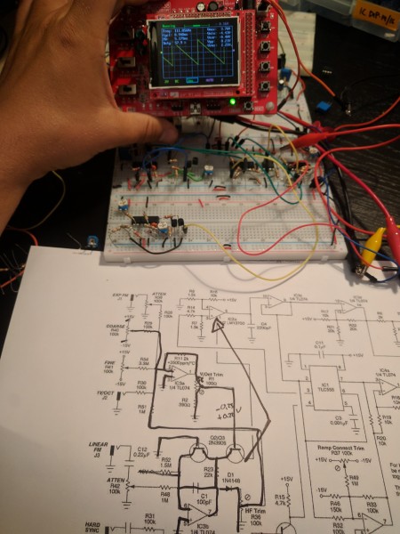
nice falling ramp there ! i got the same here
happy to hear about your progresses ! sorry i cant help more
as for my oscilloscope grid, i havent measured the squares witdth, should they be 1 cm wide? need to get a better grasp with it |
|
|
Back to top
|
|
|
fonik
Joined: Jun 07, 2006
Posts: 3950
Location: Germany
Audio files: 23
|
| Posted: Thu Aug 31, 2017 7:46 am Post subject:
|
|
|
| hedefalk wrote: | First expo working again, it was a fried Q3
Noticed now when pulling and putting back the transistor (Q3) that they give a whole lot higher frequencies when cold and slowly going down in pitch when I'm at lower frequencies. However, when I'm at high pitch, pitch actually goes up initially and turns back down after a while... Also big diff between different units.
Guess I need to learn about transistor matching and tempco now I have a bag with 100 3906's so… Just using hFe measure on cheap multimeter is no use at all, is it? |
no.
google transistor matchin ian fritz
and on a perfboard or PCB everything will be better anyways.
_________________
cheers,
matthias
____________
Big Boss at fonitronik
Tech Buddy at Random*Source |
|
|
Back to top
|
|
|
Veryfungi
Joined: Jan 02, 2018
Posts: 8
Location: forest floor usa
|
|
|
Back to top
|
|
|
Veryfungi
Joined: Jan 02, 2018
Posts: 8
Location: forest floor usa
|
|
|
Back to top
|
|
|
Veryfungi
Joined: Jan 02, 2018
Posts: 8
Location: forest floor usa
|
| Posted: Tue Jan 09, 2018 10:40 am Post subject:
|
|
|
Hello Mattias,
I found a picture of the 555-VCO with an additional led and switch. Can you tell me where to learn more about this?
Thanks |
|
|
Back to top
|
|
|
fonik
Joined: Jun 07, 2006
Posts: 3950
Location: Germany
Audio files: 23
|
| Posted: Tue Jan 09, 2018 11:37 am Post subject:
|
|
|
there are two major options how to get an VCO to dub-audio (LFO).
a) add a negative voltage to the CV summing stage, or
b) change the timing cap (C4) in this case.
b) is the most elegant solution
the LED could be fed directly from the VCO core triangle, which is positive only (IC3/pin8)
_________________
cheers,
matthias
____________
Big Boss at fonitronik
Tech Buddy at Random*Source |
|
|
Back to top
|
|
|
Veryfungi
Joined: Jan 02, 2018
Posts: 8
Location: forest floor usa
|
| Posted: Tue Jan 09, 2018 12:45 pm Post subject:
|
|
|
| Got it, thanks so much. |
|
|
Back to top
|
|
|
Veryfungi
Joined: Jan 02, 2018
Posts: 8
Location: forest floor usa
|
|
|
Back to top
|
|
|
YashN

Joined: Jun 27, 2011
Posts: 104
Location: Canada
|
| Posted: Sat Feb 17, 2018 6:35 am Post subject:
VCO-555 high-frequency troubleshooting |
|
|
With an oscilloscope, I can see waveforms generated for my VCO-555 at outputs, so I know the core is oscillating. However, I wasn't getting any sound at all.
It turns out that the output has a really high frequency, around 38kHz, therefore putting it out of audio-band!
How can I diagnose and fix this? Scope and DVM are at hand as well as the schematics and layout.
It can probably still be useful for scaring away any stray dogs but I really would like to use it as a normal audio VCO to integrate in a DIY Modular.  |
|
|
Back to top
|
|
|
elmegil

Joined: Mar 20, 2012
Posts: 2179
Location: Chicago
Audio files: 16
|
| Posted: Sat Feb 17, 2018 9:27 am Post subject:
|
|
|
Does the frequency change with your control pots?
Ususally too high means one of:
1) wrong components (too small resistor or too small capacitor)
2) short somewhere that puts more current into the core
If the frequency doesn't change, you might also have a short somewhere around the control pots and just be stuck at the high end of the oscillator's range. |
|
|
Back to top
|
|
|
YashN
Joined: Jun 27, 2011
Posts: 104
Location: Canada
|
| Posted: Sat Feb 17, 2018 10:54 am Post subject:
|
|
|
Hey elmegil, how's it going?
I will have to check again about the Coarse Control Pot: I managed to lift of a via with the -12V connection... I'll have to rewire it and tap that from somewhere else with a jumper wire. The mistake I made here was using too large a wire gauge
As for components, I think I got all if not most right as the VCO did work at one point. Maybe one failed in the meantime though.
Am I understanding this correctly?: The core does work at a higher frequency and then this is brought down subsequent to the 555? If so, I can narrow the issue down to the circtuit post 555.
Thanks for chiming in! 
| elmegil wrote: | Does the frequency change with your control pots?
Ususally too high means one of:
1) wrong components (too small resistor or too small capacitor)
2) short somewhere that puts more current into the core
If the frequency doesn't change, you might also have a short somewhere around the control pots and just be stuck at the high end of the oscillator's range. |
|
|
|
Back to top
|
|
|
elmegil
Joined: Mar 20, 2012
Posts: 2179
Location: Chicago
Audio files: 16
|
| Posted: Sat Feb 17, 2018 12:15 pm Post subject:
|
|
|
The 555 *is* the core.
If you look and see, the triangle is buffered off of the timing cap (C4)and the ramp is taken directly from pin 7 of the 555. Everything after is just wave shaping.
So your most likely problems not necessarily "in order" but kind of roughly so:
is C4 the right value?
are the resistors connecting to IC2a the right values?
Is IC2 healthy? If you used sockets, try swapping it out.
Are the resistors in the expo converter the right values (both the CV summer and the bits around IC3b and the matched transistors)?
Are the transistors themselves or the op amps themselves OK?
Is there something causing the sync input going to pin 4 of the 555 to be held low? Measure for shorts, or observe pin 4 with a scope.
I would not expect any of the stuff to do with the ramp shaping ( IC4 a & b) Triangle buffering (IC3d and associated resistors) or any of the other wave shaping to be causing this, unless possibly there is a short tying one of the 555's inputs to something it shouldn't be.
Good luck! |
|
|
Back to top
|
|
|
YashN
Joined: Jun 27, 2011
Posts: 104
Location: Canada
|
| Posted: Sat Feb 17, 2018 12:23 pm Post subject:
|
|
|
| elmegil wrote: | | The 555 *is* the core. |
Yup, this I know: "The core does work at a higher frequency and then this is brought down subsequent to the 555? If so, I can narrow the issue down to the circuit post 555. "
OK, I will check your very informative roadmap, that's going to be super helpful, thanks a lot! |
|
|
Back to top
|
|
|
elmegil
Joined: Mar 20, 2012
Posts: 2179
Location: Chicago
Audio files: 16
|
| Posted: Sat Feb 17, 2018 12:38 pm Post subject:
|
|
|
| YashN wrote: | | elmegil wrote: | | The 555 *is* the core. |
Yup, this I know: "The core does work at a higher frequency and then this is brought down subsequent to the 555? If so, I can narrow the issue down to the circuit post 555. "
OK, I will check your very informative roadmap, that's going to be super helpful, thanks a lot! |
Ah, I misread that. Bottom line is no, it doesn't work extra fast and get slowed down. C4 is the 555 timing cap and should always match the frequency of any outputs. You might want to measure what's going on with it after the voltage follower buffer though, unless your probes are high impedance they can mess with the actual frequency of the cap. |
|
|
Back to top
|
|
|
YashN
Joined: Jun 27, 2011
Posts: 104
Location: Canada
|
| Posted: Sat Feb 17, 2018 6:23 pm Post subject:
|
|
|
Had to temporarily patch my Coarse Pin 1 as indicated on the layout to the bottom of resistor R46 to get at my -12V again (I'm using -12V, +12V so did the required changes for that).
Here's what I found so far:
1. The waveforms only show when the middle pin of the Coarse Pot crosses above point between -1.4V and 0.7V approximately, and then the frequency remains fixed at around 38kHz and 39kHz approx. So not exactly out-of-audio band, but high enough that I can't hear it directly. Below that threshold, no waveforms appear at all.
2. If I use my DVM and put it on DC measurement, I do get audio out of the Pulse out when I touch the +ve probe of the DVM to the LM13700 Pin 1.
| elmegil wrote: | | is C4 the right value? |
Not sure anymore: it's a yellow-bead type, really small with the marking NC 222 on it. I can't remember if I swapped this in last time, about two years ago. Memory is a bit hazy here but I do think I had another cap at one point and it somehow was damaged, so that could be a problem.
On the upper pin of this yellow-bead cap, I do see a triangular waveform (that's looking at the layout as Fonik posted in the forums). The lower pin, however, shows nothing on the scope.
Edited to add:
I did check at IC3c P8 and P9: I get a triangular waveform at 9 but no waveform at P8. That could indicate an issue with this opamp?
| Quote: | | are the resistors connecting to IC2a the right values? |
Yes, I believe these are all OK and in fact this applies to all resistors as well. I haven't re-checked yet so I removed those points below.
| Quote: | | Is IC2 healthy? If you used sockets, try swapping it out. |
Socketed everywhere, so a swap is easy. I may be out of LM13700 for now though or I just can't find them - one disadvantage of too many projects and too many boxes currently.
| Quote: | | Are the transistors themselves or the op amps themselves OK? |
Haven't checked these but I have brand new op amps that I can swap.
| Quote: | | Is there something causing the sync input going to pin 4 of the 555 to be held low? Measure for shorts, or observe pin 4 with a scope. |
I checked it with the scope, it appears to show a +ve voltage here so I think we're good. I do have brand new 555 of the proper type for the VCO as well so a swap is possible.
Edited this as well:
So, it looks to me that the opamp IC3 could be an issue? |
|
|
Back to top
|
|
|
elmegil
Joined: Mar 20, 2012
Posts: 2179
Location: Chicago
Audio files: 16
|
| Posted: Sat Feb 17, 2018 7:40 pm Post subject:
|
|
|
| YashN wrote: |
1. The waveforms only show when the middle pin of the Coarse Pot crosses above point between -1.4V and 0.7V approximately, and then the frequency remains fixed at around 38kHz and 39kHz approx. So not exactly out-of-audio band, but high enough that I can't hear it directly. Below that threshold, no waveforms appear at all.
2. If I use my DVM and put it on DC measurement, I do get audio out of the Pulse out when I touch the +ve probe of the DVM to the LM13700 Pin 1.
|
| YashN wrote: |
| elmegil wrote: | | is C4 the right value? |
Not sure anymore: it's a yellow-bead type, really small with the marking NC 222 on it. I can't remember if I swapped this in last time, about two years ago. Memory is a bit hazy here but I do think I had another cap at one point and it somehow was damaged, so that could be a problem.
|
ok, 222 is the right VALUE, that'll be a 2200pF cap. "yellow bead" sounds like it's a ceramic axial though, you need a good film cap here.
| YashN wrote: |
On the upper pin of this yellow-bead cap, I do see a triangular waveform (that's looking at the layout as Fonik posted in the forums). The lower pin, however, shows nothing on the scope.
|
The lower pin is GROUND
So that's promising. What's the frequency of that triangular wave? Same as the output you're getting, ridiculous speed?
| YashN wrote: |
Edited to add:
I did check at IC3c P8 and P9: I get a triangular waveform at 9 but no waveform at P8. That could indicate an issue with this opamp?
|
That's really weird because they should be shorted. You sure you were measuring p8 correctly? And there's no way you should be seeing a triangle at P9 if P8 weren't connected....
Power off the circuit and check continuity from 8 to 9 as well.
| YashN wrote: |
| Quote: | | are the resistors connecting to IC2a the right values? |
Yes, I believe these are all OK and in fact this applies to all resistors as well. I haven't re-checked yet so I removed those points below.
| Quote: | | Is IC2 healthy? If you used sockets, try swapping it out. |
Socketed everywhere, so a swap is easy. I may be out of LM13700 for now though or I just can't find them - one disadvantage of too many projects and too many boxes currently.
| Quote: | | Are the transistors themselves or the op amps themselves OK? |
Haven't checked these but I have brand new op amps that I can swap.
| Quote: | | Is there something causing the sync input going to pin 4 of the 555 to be held low? Measure for shorts, or observe pin 4 with a scope. |
I checked it with the scope, it appears to show a +ve voltage here so I think we're good.
|
Ok, that sounds right, I wouldn't worry there then.
| YashN wrote: |
I do have brand new 555 of the proper type for the VCO as well so a swap is possible.
|
If you're seeing a triangle at C4/IC3 pin 9, odds are the 555 is fine.
| YashN wrote: |
Edited this as well:
So, it looks to me that the opamp IC3 could be an issue? |
Not certain..... |
|
|
Back to top
|
|
|
YashN
Joined: Jun 27, 2011
Posts: 104
Location: Canada
|
| Posted: Sun Feb 18, 2018 12:16 pm Post subject:
|
|
|
| elmegil wrote: |
ok, 222 is the right VALUE, that'll be a 2200pF cap. "yellow bead" sounds like it's a ceramic axial though, you need a good film cap here.
The lower pin is GROUND |
Yes, of course for ground
OK, since I do get the triangle output from the cap, I am going to assume this is good for now.
| elmegil wrote: | | So that's promising. What's the frequency of that triangular wave? Same as the output you're getting, ridiculous speed? |
Yes, it does appear to be exactly that: everything is at 38-40kHz, at least when I go past the threshold on the Coarse Pot. Below that threshold, I get nothing.
| elmegil wrote: | | That's really weird because they should be shorted. You sure you were measuring p8 correctly? And there's no way you should be seeing a triangle at P9 if P8 weren't connected.... |
Definitely sounds like I inadventently moved my Coarse Pot in between readings: that would explain why I3P8 then gave me nothing.
From newer measurements, it looks like they're all connected properly. I will try to include the BMP from my small scope below. It's also a DSO, so that came in handy actually. I am liking it so far - portable enough for my Modular DIY builds.
Attached: 555 Pins 2, 3, 6, 7 + C4
| Description: |
|

Download (listen) |
| Filename: |
555P2.BMP |
| Filesize: |
38 KB |
| Downloaded: |
288 Time(s) |
| Description: |
|
Download (listen) |
| Filename: |
555P3.BMP |
| Filesize: |
38 KB |
| Downloaded: |
278 Time(s) |
| Description: |
|
Download (listen) |
| Filename: |
555P6.BMP |
| Filesize: |
38 KB |
| Downloaded: |
282 Time(s) |
| Description: |
|
Download (listen) |
| Filename: |
555P7.BMP |
| Filesize: |
38 KB |
| Downloaded: |
267 Time(s) |
| Description: |
|
Download (listen) |
| Filename: |
C4.BMP |
| Filesize: |
38 KB |
| Downloaded: |
276 Time(s) |
Last edited by YashN on Sun Feb 18, 2018 2:22 pm; edited 1 time in total |
|
|
Back to top
|
|
|
elmegil
Joined: Mar 20, 2012
Posts: 2179
Location: Chicago
Audio files: 16
|
| Posted: Sun Feb 18, 2018 12:33 pm Post subject:
|
|
|
So let's talk our way through control voltages.
wiper of the coarse pot should swing from -15V to +15V
Set the exp FM pot all the way CCW and the fine pot as close to center as you reasonably can (you could measure it at the wiper and make sure it was 0V).
Set the linear FM pot all the way CCW as well.
IC3a pin 1 should output something close to -.02 x the voltage at the coarse pot's wiper -- for example if the wiper is set at 10V, the output of the op amp should be -.2V
The output of the wiper of the 100R V/Oct trimmer (connects to base of Q3) should be a little bit less, somewhere above .16V when the coarse pot is at 10V.
When you change the coarse pot, these should all move in the direction you expect.
Verify all that looks right and then we can move on.... |
|
|
Back to top
|
|
|
YashN
Joined: Jun 27, 2011
Posts: 104
Location: Canada
|
| Posted: Sun Feb 18, 2018 12:54 pm Post subject:
|
|
|
Testing if the linked pics work better for the rest of the measurements from the scope here. This is for IC3 Pins 8, 9 and 10:
 IC3P8 IC3P8
 IC3P9 IC3P9
 IC3P10 IC3P10 |
|
|
Back to top
|
|
|
|

 Forum index » DIY Hardware and Software » Thomas Henry designs