| Author |
Message |
parasitk

Joined: Sep 21, 2008
Posts: 69
Location: NYC
|
 Posted: Thu Oct 09, 2008 5:48 pm Post subject: Posted: Thu Oct 09, 2008 5:48 pm Post subject:
|
  |
|
I hate to say it, but that diagonal look never did it for me. Just seems like a lot of wasted space.  |
|
|
Back to top
|
|
 |
urbanscallywag

Joined: Nov 30, 2007
Posts: 317
Location: sometimes
|
| Posted: Thu Oct 09, 2008 5:55 pm Post subject:
|
|
|
Another Buchla question (I have many more...).
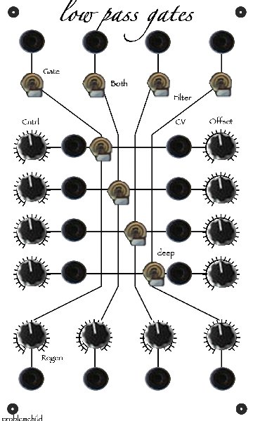
I wanted to clarify, are the knobs on the LPG offset control? There aren't any CV attenuators? |
|
|
Back to top
|
|
|
Luka

Joined: Jun 29, 2007
Posts: 1003
Location: Melb.
|
|
|
Back to top
|
|
|
bugfight

Joined: Aug 02, 2007
Posts: 188
Location: Arlington, TX USA
|
| Posted: Fri Oct 10, 2008 11:06 am Post subject:
|
|
|
| djthomaswhite wrote: | | Scott at Bridechamber has given me the inital green light that the two panel designs |
awesome! i'll be ordering both |
|
|
Back to top
|
|
|
phdinfunk
Joined: Jun 04, 2008
Posts: 119
Location: Taiwan
|
| Posted: Fri Oct 10, 2008 11:35 am Post subject:
|
|
|
| neandrewthal wrote: | | I'm going to pay homage to the orginal buchla version with a quad unit. I can fit all 4 of them in the same space as one "deluxe" version. If I really need to mix multiple signals I can use an external mixer, or just drive several units in parallel and take the summed output. I think I will link all the CV inputs with switching jacks, and also use them to subtract the individuals outputs from the summed out as /mr suggested. Much more flexible and space effective IMO. |
My intention is similar. I like the look of the Buchla. I'll make a quad unit but put CV attentuation on the bottom (because I do like having both CV atten and offset on a VCA). Then I think I'll put a Sum output out to the right of the outputs (mix them all together).
With my other four, hmmmm.... I'll impliment the res function in some way... Maybe do two duals. That's just too damned cool for me to be a purist and ignore it.
--Jonathan |
|
|
Back to top
|
|
|
BananaPlug

Joined: Jul 04, 2007
Posts: 307
Location: Philly
Audio files: 5
|
Posted: Sat Oct 11, 2008 6:38 am Post subject:
Subject description: Using them in series? |
|
|
| Anybody have a sample of what two of the LPGs in series sounds like? How useful is that? |
|
|
Back to top
|
|
|
phdinfunk
Joined: Jun 04, 2008
Posts: 119
Location: Taiwan
|
| Posted: Sun Oct 12, 2008 12:17 am Post subject:
setups. |
|
|
Here in Taiwan I haven't got a computer at my house yet, so I'm drawing my designs by hand (no internet at home, did I mention I'm getting a lot done lately, LOL). Unfortunately that means I cannot post a pic yet.
I like the traditional Buchla Diagonal look and have discovered that, on a somewhat larger than standard panel, it is aesthetically pleasing to add the resonance knobs under the mode switch knobs. Also, for my CV inputs, I think having two inputs per Gate and having a dual-pot attentuation knob pan between them will be most useful for live performance.
--Jonathan, who will soon try to communicate with the Chinese at the internet cafe enough to get a drawing scanned... |
|
|
Back to top
|
|
|
cyclotron

Joined: Sep 27, 2008
Posts: 6
Location: US
|
| Posted: Tue Oct 14, 2008 7:24 am Post subject:
|
|
|
2 here...
sent email w info per request |
|
|
Back to top
|
|
|
LektroiD

Joined: Aug 23, 2008
Posts: 1019
Location: Scottish Borders
Audio files: 2
G2 patch files: 2
|
| Posted: Wed Oct 15, 2008 3:57 am Post subject:
|
|
|
Just bought all the parts for these, as per parts list here:
http://electro-music.com/forum/download.php?id=14435
I got one set of slow vactrols and one set of fast, just so both my boards are different. Any idea when the boards are likely to be shipped (if they haven't already)? I know there's a postage lag across the pond, but my soldering iron is quivering in anticipation.
Last edited by LektroiD on Wed Oct 15, 2008 9:26 am; edited 1 time in total |
|
|
Back to top
|
|
|
numbertalk

Joined: May 05, 2008
Posts: 992
Location: Austin, TX
Audio files: 5
|
| Posted: Wed Oct 15, 2008 6:32 am Post subject:
|
|
|
Do you mind clarifying for the numbskulls (which admittedly might just be me  ) which switch position corresponds to which mode for the 3PDT toggle? For example, when the top 2 sets of poles ("top" referring to how the switch lugs are shown and oriented in the blown-up switch diagram on the schematic), which mode is this, then the middle "off" (or "open") setting then finally when the bottom 2 sets of poles are connected. ) which switch position corresponds to which mode for the 3PDT toggle? For example, when the top 2 sets of poles ("top" referring to how the switch lugs are shown and oriented in the blown-up switch diagram on the schematic), which mode is this, then the middle "off" (or "open") setting then finally when the bottom 2 sets of poles are connected. |
|
|
Back to top
|
|
|
djthomaswhite

Joined: Nov 22, 2007
Posts: 140
Location: Orange, CA
|
| Posted: Wed Oct 15, 2008 9:48 am Post subject:
Updates |
|
|
Boards are being ordered on Monday October 20th from the Fab House. They will take 10 business days to be made and 2 after to ship to me. All orders will be shipped within a few days to a week of the boards arrival at my house.
The switch action may be best reported by Matthias Fonik. He has built this with 3PDT and I have only used Rotary. But, It would appear to be like the original:
Up - Filter
Middle - Both
Down - Amplifier (Gate)
Can someone verify this who has built Matthias' board layout?
Thanks guys!
Getting REAL close to order date!!!
_________________
Thomas
www.naturalrhythmmusic.com/diy.html |
|
|
Back to top
|
|
|
panele

Joined: Apr 13, 2008
Posts: 19
Location: mainz, germany
|
| Posted: Wed Oct 15, 2008 12:16 pm Post subject:
|
|
|
i`ll take 2 pcbs
thank you |
|
|
Back to top
|
|
|
numbernone
Joined: Aug 16, 2006
Posts: 477
Location: new york city
|
| Posted: Wed Oct 15, 2008 2:01 pm Post subject:
|
|
|
OK this is a question from an outsider, as I am doing my own boards to suit my own purposes. I am also using the second Fonik layout incorporating the 3/2 vactrol. This allows me to make a very very small board which is a top priority for me...
Why was the decision made to use the first layout with the pair of vactrols? Mainly to give the opportunity to use different types?
That is all. Peace be to all LPG thwappers and thwackers. |
|
|
Back to top
|
|
|
djthomaswhite
Joined: Nov 22, 2007
Posts: 140
Location: Orange, CA
|
| Posted: Wed Oct 15, 2008 2:37 pm Post subject:
|
|
|
I used the dual design like the prototype I had built in the final design. It does allow for one of each type of Vactrol to be used in the two slots, but I don't know how useful this is in all honesty. You can likely modify my board to use the single Vactrol but I am not sure how. Any ideas out there?
Thomas
_________________
Thomas
www.naturalrhythmmusic.com/diy.html |
|
|
Back to top
|
|
|
Luka
Joined: Jun 29, 2007
Posts: 1003
Location: Melb.
|
| Posted: Wed Oct 15, 2008 3:34 pm Post subject:
|
|
|
i really wanted some of these boards but looks like it wont happen since out dollar bombed out my budget for this stuff had diminished by almost a half. shame.
so thomas, did you tweak many values and signal flow from matthias' design. i have a bunch of them on pnp ready to go, so just wondeing if adding a deep switch and resonace will bring it in line with yours
_________________
problemchild
melbourne australia
http://cycleofproblems.blogspot.com/
http://www.last.fm/user/prblmchild |
|
|
Back to top
|
|
|
djthomaswhite
Joined: Nov 22, 2007
Posts: 140
Location: Orange, CA
|
| Posted: Wed Oct 15, 2008 5:25 pm Post subject:
|
|
|
Hi Luka,
If you read back through this forum topic you will find a listing of all changes that have come about. You could also print my modified schematic to compare to the one on Matthias' website. The main differences are:
1. Addition of resonance circuit (1 pot, 1 resistor and some routing changes)
2. Addition of the "Deep" Switch (simple offset switch with value set by resistor)
3. Additional Mixer section for multiple audio ins
4. Additional Mixer section for multiple CV ins
5. Capacitor between pins 13 and 14 of the TL084 IC when using the resonance mod
6. PCB mounted resonance and offset pots
That is about it. All of these could be added to the PCB layout on the Fonik site fairly easily. This has proven to be a great group and any feedback you request will likely be answered. Soon there will be a great many more people "in the know" about how lopass gates work and what mods can be done to this circuit that I couldn't dream up in my limited knowledge. Thanks!
T
_________________
Thomas
www.naturalrhythmmusic.com/diy.html |
|
|
Back to top
|
|
|
Luka
Joined: Jun 29, 2007
Posts: 1003
Location: Melb.
|
| Posted: Wed Oct 15, 2008 6:07 pm Post subject:
|
|
|
thanks thomas
you have done great with this project
i wish international financial situation hadn't got so sticky and i could have joined in on your group buy
i have a quad panel design now ready to go too
_________________
problemchild
melbourne australia
http://cycleofproblems.blogspot.com/
http://www.last.fm/user/prblmchild |
|
|
Back to top
|
|
|
neandrewthal

Joined: May 11, 2007
Posts: 672
Location: Canada
|
| Posted: Wed Oct 15, 2008 8:44 pm Post subject:
|
|
|
| Luka wrote: |
i have a quad panel design now ready to go too |
Pic or stfu
_________________
" I went through quite a few trannies til I found one I liked" - Wild Zebra |
|
|
Back to top
|
|
|
Luka
Joined: Jun 29, 2007
Posts: 1003
Location: Melb.
|
|
|
Back to top
|
|
|
neandrewthal
Joined: May 11, 2007
Posts: 672
Location: Canada
|
| Posted: Thu Oct 16, 2008 9:03 am Post subject:
|
|
|
| Luka wrote: | | well my layouts are a bit different from the norm so it probably isnt much use to most poeple. |
That's why I like to see them  My layout keep getting further and further from MOTM standard, so it's always inspirational to see someone else phucking with the phormat. I like how you kept the diagonal thing going without wasting too much space. My layout keep getting further and further from MOTM standard, so it's always inspirational to see someone else phucking with the phormat. I like how you kept the diagonal thing going without wasting too much space.
_________________
" I went through quite a few trannies til I found one I liked" - Wild Zebra |
|
|
Back to top
|
|
|
machine.cuisine
Joined: Jul 20, 2007
Posts: 61
Location: ks
Audio files: 4
|
| Posted: Thu Oct 16, 2008 2:54 pm Post subject:
|
|
|
| djthomaswhite, your videos on youtube are awesome demos. I can't wait to use build and use the LPG. |
|
|
Back to top
|
|
|
phdinfunk
Joined: Jun 04, 2008
Posts: 119
Location: Taiwan
|
| Posted: Thu Oct 16, 2008 9:00 pm Post subject:
Parts Kits... |
|
|
Is anyone/Has anyone organized parts kits availability?
Or maybe made a BOM that has Mouser Parts Numbers.
I have enough time that I could make a BOM Mouser Compliant IF I won't be duplicating someone else's work.
Then you all could just ship the BOM off to mouser, pay them and wait... oh yea, then you'll need to solder together your modules  . .
Thanks,
Jonathan |
|
|
Back to top
|
|
|
djthomaswhite
Joined: Nov 22, 2007
Posts: 140
Location: Orange, CA
|
|
|
Back to top
|
|
|
djthomaswhite
Joined: Nov 22, 2007
Posts: 140
Location: Orange, CA
|
| Posted: Sat Oct 18, 2008 10:26 am Post subject:
|
|
|
Hi all,
Reminders have been sent out one last time for those who have expressed interest but have not paid for the PCB's. I am not trying to be a pest, just making sure in the swirl of DIY-madness that you do not forget about this "one time run" of these PCBs.
There are less than 2 days left to get an order in! If you are thinking about this but on the fence you need to decide by Midnight tomorrow (Sunday, USA Pacific time) if you want to place an order.
I will accept order requests all the way until when I wake up for work Monday morning. So, if at the last minute you decide you want to get in on this send me an email. I will invoice you via PayPal on Monday and consider you will in fact pay for your PCB request. If not I may end up with extras but I will take that risk to make sure all who want to can be involved in this community build.
Status of testing: The PCB is solid. I am going to use a flamethrower and sledgehammer later today for the final round of stress testing... HA! I will add bypass caps maybe. (EDIT: I will not be adding bypass caps. My power filtering has them in there less with between 1 and 2 inches maximum trace to each of the two IC's. If you find them necessary adding them will not be hard with a little extra solder and the bonus ground pads on the bottom of the PCB). In a little less than a month from now you should have your PCBs and maybe even have them built already. Thanks for your continued support of this project!
Thomas
_________________
Thomas
www.naturalrhythmmusic.com/diy.html
Last edited by djthomaswhite on Sat Oct 18, 2008 6:18 pm; edited 1 time in total |
|
|
Back to top
|
|
|
numbertalk
Joined: May 05, 2008
Posts: 992
Location: Austin, TX
Audio files: 5
|
| Posted: Sat Oct 18, 2008 1:41 pm Post subject:
|
|
|
| djthomaswhite wrote: | | Really though I will be adding bypass caps to the IC's to make sure they work as planned (ie. transparent in sound but solid in design practice) |
Are you planning to add spots for these on the boards & update the component placement page?
Glad it's coming along! Thanks! |
|
|
Back to top
|
|
|
|

 Forum index » DIY Hardware and Software