Joined: Jan 14, 2010 Posts: 5973 Location: Moon Base
Audio files: 709
Posted: Sun Jul 19, 2015 3:55 am Post subject:
Shock_Hazard wrote:
Some great stuff (like the fantastic synth in the previous post) seems to be getting lost in these annual threads, it deprives the forum of new threads and subsequent discussion by confining things to one thread.
I somewhat agree but I think that if everybody would make a new thread for each build things would actually get lost in it must faster.
Not that I would mind if there was a seperate thread with more info for every thing posted, but this one functions as a nice overview
and I always love these threads to get some inspiration. Personally I do often make a seperate thread with more info and than link
it from this one. (which I will also be doing with the next thing I'll be posting here shortly).
good looking that synth .. ar you sure it is a first one _________________ Jan
also .. could someone please turn down the thermostat a bit.
9 3 4 .. erm .. not 13 then? .. hmm, ah eight! .. yeah yeah as in 8647 .. 47 is an 88 .. pwew .. numbles!
Joined: Jan 14, 2010 Posts: 5973 Location: Moon Base
Audio files: 709
Posted: Sun Jul 19, 2015 11:22 am Post subject:
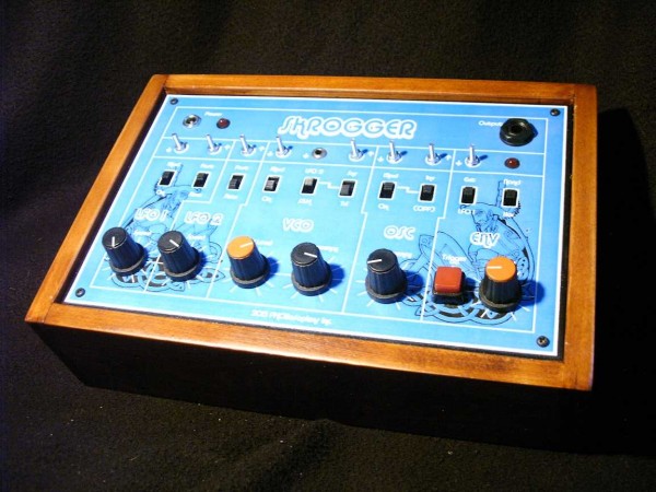
Skrogger
I finished the Skrogger, a simple Lunetta synth made with some chips and switches that Dave (skrog productions) send me.
more info and photos can be found here.
Skrogger - 13.jpg
Description:
Skrogger
Filesize:
92.85 KB
Viewed:
545 Time(s)
This image has been reduced to fit the page. Click on it to enlarge.
Personally I do often make a seperate thread with more info and then link it from this one.
Maybe that should be encouraged as the "done thing": post some photos in this thread, like an index of creations, but have more info & discussion in a separate thread linked from each post. That way there can be more details and more activity and more everything for each person's devices
Joined: Mar 28, 2006 Posts: 1472 Location: Kansas City, Mo USA
Audio files: 45
Posted: Mon Jul 20, 2015 11:25 am Post subject:
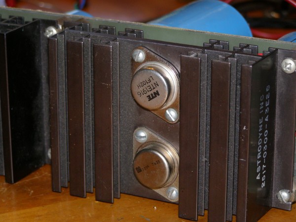
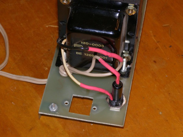
Repairs to my Aries Power Supply
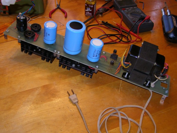
One of the advantages of DIY is that one learns how to repair one's own equipment. My vintage Aries power supply still works to spec. Over the years I've had to replace the filter capacitors and the +15v rectifier and voltage regulator (my most recent repair). Attached are photographs with comments about the power supply and repairs.
The NTE1916 is the replacement Voltage Regulator. The pins (underneath) are not centered, thus the part can only mount in one direction. When I first installed this regulator, it didn't work. Then I looked and noticed that the labeling is "upside down" compared to the original. I checked the datasheet and confirmed that the pins were reversed! A quick swap on the pin connections did the trick.
The original Aries had two serious and hazardous design issues: 1) The mains voltage ran through an exposed fuse holder and, 2) the mains voltage ran through a front-panel mounted toggle switch. My solution was to do away with the power switch (it does not really need one anyway) and to replace the exposed fuse holder with a panel mount style holder.
While I have replaced this power supply with MFOS power supplies, this power supply will live on as a bench power supply (+15, -15, and +5 volts) and a backup power supply (just in case!).
AriesPowerSupply1.jpg
Description:
Filesize:
852.14 KB
Viewed:
543 Time(s)
This image has been reduced to fit the page. Click on it to enlarge.
AriesPowerSupply3.jpg
Description:
Filesize:
742.89 KB
Viewed:
514 Time(s)
This image has been reduced to fit the page. Click on it to enlarge.
AriesPowerSupply2.jpg
Description:
Filesize:
854.51 KB
Viewed:
545 Time(s)
This image has been reduced to fit the page. Click on it to enlarge.
Posted: Wed Jul 22, 2015 12:06 am Post subject:
Re: Repairs to my Aries Power Supply
kkissinger wrote:
The NTE1916 is the replacement Voltage Regulator. The pins (underneath) are not centered, thus the part can only mount in one direction. When I first installed this regulator, it didn't work. Then I looked and noticed that the labeling is "upside down" compared to the original. I checked the datasheet and confirmed that the pins were reversed! A quick swap on the pin connections did the trick.
Oh yes, I had the same problem with my 2n3055 power trannies in my Formant modular power supply. I had asked my local parts dealer how to connect them and he gave me a wrong pinout. I did not check the datasheet and finished the PSU. Unfortunately the PSU worked The output power was reduced and the output voltage had a kind of saw overtone, but this effect occured later when I added more and more modules. It took a long time for me to find that error
Hi Kevin! What made you decide to replace the PS with a new one? Also you did away with the front panel/switch. Does it simply power up when plugged in, or does your new power supply have a switch? I plan on learning as much as I can from you. As stated on my introduction post, I have a recent Aries addition to my synth-family. The power supply was off on the positive side, I replaced the regulator and it is working now, albeit not exactly 15, it is around 15.2+ VDC.. The - is at around -15.02. Also, I have been guessing what the +5 is supplied for? Is it for the osc CV outs on the keyboard? Thanks, John C. in Norman OK
No matter how ugly the new baby really is you have to show it off.
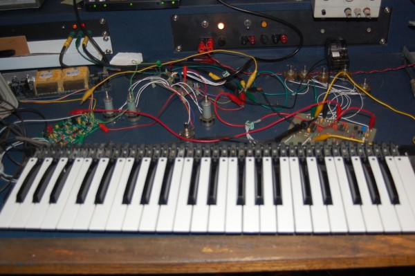
Over a year of messing about finally have something that makes musical type noise. It didn't help I ended up putting it aside for a bit in frustration then finding out the problem was bad IC's. Got the basics done can move on to more interesting stuff to add as well as putting it all in some kind of enclosure.
XR2206 VCO, Yu Synth ADSR, MFOS keyboard controller, working on a VCA this evening. The keyboard is from an old Lowery organ a friend junked.
DSC_0141.JPG
Description:
Filesize:
655.57 KB
Viewed:
455 Time(s)
This image has been reduced to fit the page. Click on it to enlarge.
Joined: Mar 28, 2006 Posts: 1472 Location: Kansas City, Mo USA
Audio files: 45
Posted: Mon Aug 17, 2015 5:10 pm Post subject:
Modorange wrote:
Hi Kevin! What made you decide to replace the PS with a new one? Also you did away with the front panel/switch. Does it simply power up when plugged in, or does your new power supply have a switch? I plan on learning as much as I can from you. As stated on my introduction post, I have a recent Aries addition to my synth-family. The power supply was off on the positive side, I replaced the regulator and it is working now, albeit not exactly 15, it is around 15.2+ VDC.. The - is at around -15.02. Also, I have been guessing what the +5 is supplied for? Is it for the osc CV outs on the keyboard? Thanks, John C. in Norman OK
The reasons that I replaced it was because I already had all the parts for a new (higher-capacity) power supply. I believe the Aries Power supply was a bit challenged to drive all the modules that I added over the years. Also, I really need a bench power supply and the old power supply is more than adequate for that. The new power supply is lighter, too. Incidentally, I am using the MFOS 3 Amp power supply -- I now have two of them in my synthesizer. Indeed, I don't have an on/off switch -- I just plug into a power strip that has a switch. I'd like to add a power switch at some point but it isn't really high-priority. _________________ -- Kevin http://kevinkissinger.com
There's a video in the matrixsynth link I sent before. It is a standard (Serge style) programmer sequencer touch keyboard beast, with a custom "variable note length" mode that takes in an analog waveform and sets note lengths based on windowed comparators.
Custom boards
Arduino / hacked Narbotic Midivox MIDI clock divider / synced LFO generator
Quad gated comparators to enable step mutes by turning each pot to “zero”
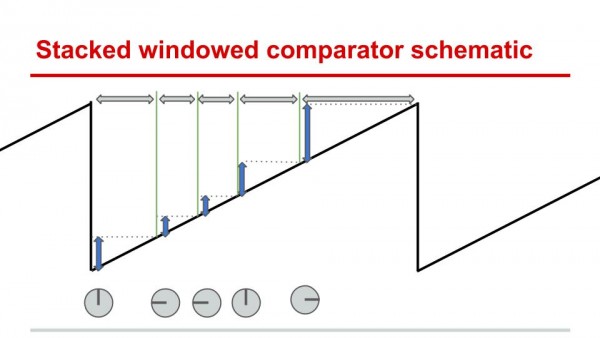
16 stacked windowed comparators to enable continuously variable note lengths i.e. “microtemporal” and microtonal sequencing.
The ribbon goes to an Appendage (hiding just behind the beast).
[/b]
Untitled presentation.jpg
Description:
Schematic of the "stacked comparator" triggering scheme.
Filesize:
39.86 KB
Viewed:
310 Time(s)
This image has been reduced to fit the page. Click on it to enlarge.
16 stacked windowed comparators to enable continuously variable note lengths i.e. “microtemporal” and microtonal sequencing.
That looks interesting
heh, sorry, actually the whole device looks very nice, but this part drew my attention .. as in .. would like to try something like that for my own synth.
How does it work exactly?
I get the microtemporal bit from the drawing, but it is not clear to me where tonal information comes from.
A quick sketch here looked like here, thought it might be nice to have a selection for the trigger outs to go to one out of three outs. _________________ Jan
also .. could someone please turn down the thermostat a bit.
9 3 4 .. erm .. not 13 then? .. hmm, ah eight! .. yeah yeah as in 8647 .. 47 is an 88 .. pwew .. numbles!
I get the microtemporal bit from the drawing, but it is not clear to me where tonal information comes from.
The top four rows are all CV knobs. There are three jacks to the right of each output - Out (pitch, or whatever CV), Mix (gets mixed with Out - good for making arpeggiators), and Gate. Gate sends a pulse for every step that isn't dialed to zero.
The bottom (fifth) row is the "note length" microtemporal row. It compares any input waveform to voltage windows set by each knob. When the analog input is within a window, it sends a trigger to the corresponding step - just like tapping one of the touch keyboard pads. A sawtooth will trigger the steps sequentially - other waveforms, not so much.
Watch a video on a serge programmer/sequencer to get a better feel for the basic functionality - any stage can be triggered at any point.
Thanks! _________________ Jan
also .. could someone please turn down the thermostat a bit.
9 3 4 .. erm .. not 13 then? .. hmm, ah eight! .. yeah yeah as in 8647 .. 47 is an 88 .. pwew .. numbles!
Joined: Jul 18, 2015 Posts: 12 Location: New Jersey
Posted: Thu Sep 10, 2015 11:42 am Post subject:
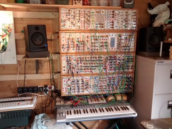
This is my 2nd modular I'm working on. Inspired by the Moog System 35. The panels are 8.75"x2" and the cabinet is 4ft wide, so pretty close to Moog specs. All the circuits were hand soldered on breadboard and the Aluminum panels were spray painted black, sorry no labels, I know what everything does so that's all that matters, plus it still looks cool this way.
13 completed modules so far:
3x Thomas Henry 555 VCOs
3x Mixers
2x Yusynth VCAs
1x Yusynth Steiner VCF
1x Yusynth MiniMoog clone filter (How could I not??)
1x Dual Thomas Henry LFO
1x Triple Thomas Henry AR generator
1x Multiples
Almost half way complete but I'm away at school and won't be able to work on it for a while unfortunately. I completed all this in about 7 weeks during the summer. I spent more money on better parts and had more patience so this is a huge improvement in quality over my first system so far.
Joined: Jul 18, 2015 Posts: 12 Location: New Jersey
Posted: Fri Sep 11, 2015 9:58 am Post subject:
dougseidel wrote:
Hi there - what are those nice boards you are using?
I like the no labels thing - very nice
Those are breadboards from adafruit. They are a bit more expensive but they are great quality, no lifted pads or anything.
http://www.adafruit.com/products/591
Joined: Mar 11, 2014 Posts: 746 Location: New Zealand
Audio files: 41
Posted: Mon Sep 14, 2015 11:10 pm Post subject:
Mmm. This is one of those really boring sounding modules that add a lot to a patch. Yusynth Gated Slew. Everything I've built by Yves Usson is utterly amazing.
The panel is a 3mm mirrored plastic that my panel man, Rullywow found. Beautiful! It looks a lot nicer in real life, mirrored stuff is annoying to photograph.
Only part I'm annoyed with is the pot. I'm tempted to do a v0.2 layout with a 16mm pot (but the same pot/jack/switch layout, so I can keep that beautiful panel with the new layout!)
Joined: Dec 17, 2009 Posts: 497 Location: Rosmalen, Netherlands
Posted: Tue Sep 15, 2015 5:05 am Post subject:
Nice!
Yeah those pots, aren't the greatest, I wonder if you can get a different pot in that space though, maybe one of the Alpha 9mm ones with bushing? Hole diameter will need to be something like 7mm I believe.
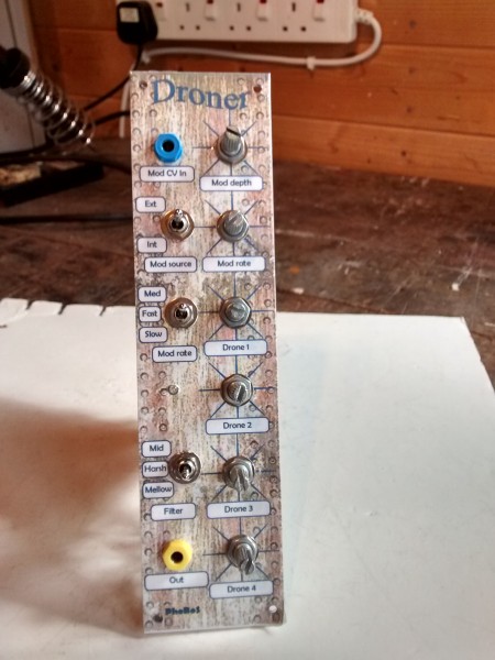
Latest build - a four 40106 drone module by PhoBoS, with a few mods, chiefly adding in an external CV input for the PWM, which allows control by an LFO or any other CV source. I also added extra caps on a switch to give a range of low-pass filter options on the output.
The things in black insulating tape are home-rolled vactrols.
Peter
Droner front panel.jpg
Description:
Filesize:
1.37 MB
Viewed:
325 Time(s)
This image has been reduced to fit the page. Click on it to enlarge.
Droner circuit board.jpg
Description:
Filesize:
1.59 MB
Viewed:
329 Time(s)
This image has been reduced to fit the page. Click on it to enlarge.
You cannot post new topics in this forum You cannot reply to topics in this forum You cannot edit your posts in this forum You cannot delete your posts in this forum You cannot vote in polls in this forum You cannot attach files in this forum You can download files in this forum

 Forum index » DIY Hardware and Software


 here, thought it might be nice to have a selection for the trigger outs to go to one out of three outs.