Joined: Mar 11, 2014 Posts: 746 Location: New Zealand
Audio files: 41
Posted: Mon Oct 17, 2016 9:12 pm Post subject:
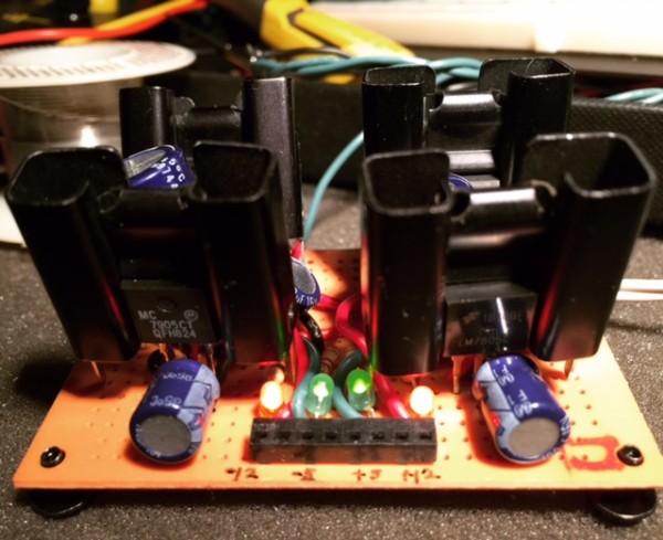
Buchla 208 Random circuit. Somewhat shonky random (it repeats after 127 steps or so), but with four outputs, and clocked. Two trace cuts were needed, and two blue wires. Other than that, I'm very happy with how it came out.
I'ma gonna experiment me with some krell patching now. dcramer has been teasing me with his youtube vids for too long!
that equalizer looks nice and i wish i had íncluded the separate channel outputs on my own...
btw. i'm sure i have a bug somewhere in my build and think i'll have to look over it again, does your upper and bottom section output get's affected by the pots from the other section? _________________ https://soundcloud.com/bastian-j
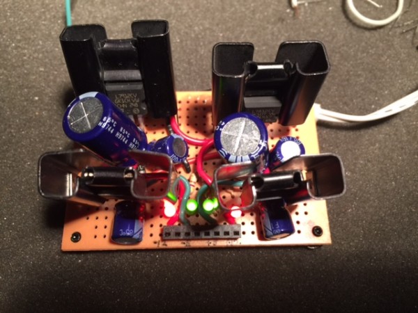
on the 2nd picture from below when I look at the colors it looks like there might be a mistake either by you or the manufacturer.
all the colors of the wires coming from the upper board in this picture to the lower board are running next to each other except l p g ( on the upper board) colors are white brown green, but on the lower board they are brown white green.
now maybe they supposed to be like that, in that case this post was never written
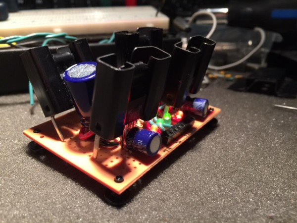
I am working on a new filter on breadboard, but I was getting a lot of 60Hz interference from the power supply that I also had on breadboard. I moved the power over to a little strip board and soldered it all together. Now I should be able to finish the filter without any problems.
image1 (1).JPG
Description:
Filesize:
122.46 KB
Viewed:
456 Time(s)
This image has been reduced to fit the page. Click on it to enlarge.
image2.JPG
Description:
Filesize:
120.01 KB
Viewed:
427 Time(s)
This image has been reduced to fit the page. Click on it to enlarge.
image3.JPG
Description:
Filesize:
127.21 KB
Viewed:
410 Time(s)
This image has been reduced to fit the page. Click on it to enlarge.
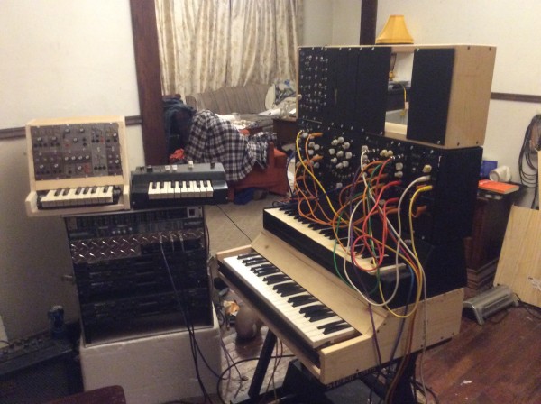
Decided to work on the stack of projects getting left behind.
Bought these PAIA 4700 modules cheep on eBay. I just keep moving them out of my road, so I decided to do something.
I didn't need another full keybed. My MIDI to CV converters will do Volt/HZ, but I decided to include a 16 note keybed to use up my Ken Stone 16 note key matrix circuit I built for anouther project, and didn't use.
Has 2 VCOs, AR, ADSR, 2 Balanced modulators used as VCAs, low pass VCF, and inverter buffer module.
IMG_0540.JPG
Description:
Filesize:
1.49 MB
Viewed:
358 Time(s)
This image has been reduced to fit the page. Click on it to enlarge.
Wow. That's a lot of circuitry. Very impresive Alanp
Made a huge decision myself today. I'm buying a module. Big jump for me, considering everything I have is on perf. Have never even built a kit module, or purchased a board.
This Module already had an 8 channel clock devider and an arbitrairy trigger generator programmed, see THIS
Not realy a new build, but a new programmed section: I've added Euclidean Triggers to this module.
8 channels, each from 0 (no triggers) to 32 possible triggers.
In this video the sounds are coming from a (slightly modified) dsp_M8 build
edit: bad link and typo Last edited by Grumble on Thu Dec 15, 2016 12:20 am; edited 1 time in total
Thanks for that! I didn't know about the existence of this Ornament + Crime module but looking at it, I got a whole set of new ideas (well.... for me they're new )
I got my inspiration of a thread here on EM, which is referring to THIS video on Youtube.
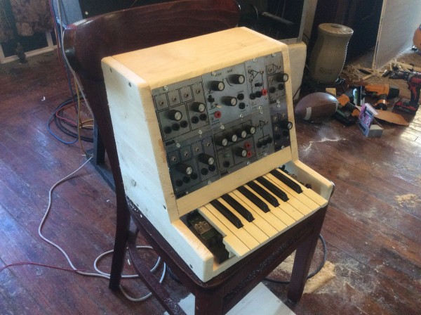
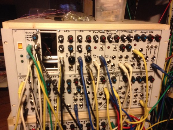
Sorry that i'm cheating a bit and present here a cabinet with a open hole, but i swear the main stripboard for this place is ready (fingers crossed) and is on top of the cabinet for those who can't believe
The missing module is a +/-5V quantizer i build from Fonik's schematic, but accidentally as i drilled the front panel i forgot that i wanted to try it out with attentuating pots on the input and if it fit's well have to look for another filler of the left space, which i first thought should be a simple 2 channel CGS mixer... you simply can't have enough mixers...
From left to right beginning in the upper row:
PSU switch with indicator LED's, Scott Stites Quantizer, big hole, 2xLPG, 2xBuchla enevelope follower, CGS voltage processor, CGS serge VCS,
bottom row: CGS CV Cluster, Buchla 291 BPF, CGS Serge Phaser, Serge Comparator (only 2 sections), from the Buchla SOU: Integrator, S&H, stored random voltages & at least another Serge VCS.
IMG_0133.JPG
Description:
front view
Filesize:
768.69 KB
Viewed:
265 Time(s)
This image has been reduced to fit the page. Click on it to enlarge.
IMG_0135.JPG
Description:
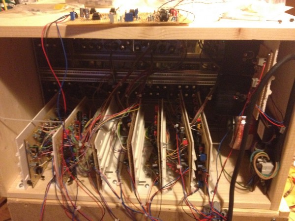
back view
Filesize:
775.14 KB
Viewed:
262 Time(s)
This image has been reduced to fit the page. Click on it to enlarge.
You cannot post new topics in this forum You cannot reply to topics in this forum You cannot edit your posts in this forum You cannot delete your posts in this forum You cannot vote in polls in this forum You cannot attach files in this forum You can download files in this forum

 Forum index » DIY Hardware and Software