| Author |
Message |
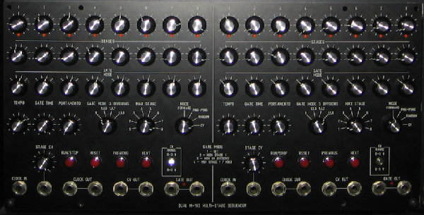
The Alison Project

Joined: Jul 21, 2006
Posts: 187
Location: Canada
Audio files: 2
|
|
|
Back to top
|
|
 |
ryktnk

Joined: Apr 24, 2008
Posts: 285
Location: london
Audio files: 1
|
 Posted: Wed Dec 17, 2008 1:18 pm Post subject: Posted: Wed Dec 17, 2008 1:18 pm Post subject:
|
  |
|
oh la la !
That looks great, and big.
Well done.
-ryk |
|
|
Back to top
|
|
|
lexvortex

Joined: May 14, 2008
Posts: 155
Location: Toronto
|
|
|
Back to top
|
|
|
del_poolp
Joined: Aug 28, 2006
Posts: 12
Location: France
|
|
|
Back to top
|
|
|
numbernone
Joined: Aug 16, 2006
Posts: 477
Location: new york city
|
| Posted: Thu Dec 18, 2008 12:05 pm Post subject:
|
|
|
Got my switches today LIGHTNING SPEED too. They look great.
If some kind soul would like to post an FPD file for the switch cutouts and mounting holes, I would be beyond eternally appreciative. I am a front panel designer virgin, and would like someone gentle to introduce me! |
|
|
Back to top
|
|
|
ryktnk
Joined: Apr 24, 2008
Posts: 285
Location: london
Audio files: 1
|
| Posted: Thu Dec 18, 2008 3:57 pm Post subject:
|
|
|
Hello del_poolp
The panel looks very nice !
But you have missed out a switch
and need to change the "mode" switch.
Have a look at the panel wiring PDF as there
is a 4-way switch for the sequencer mode [this
used to be random on/off on my old panel picture]
Also there is a new 4-way switch which is for the stage
subdivisions, sorry.
If you would like to add a "RYK" logo I can send
one over, very flattered !
cheers
-ryk |
|
|
Back to top
|
|
|
del_poolp
Joined: Aug 28, 2006
Posts: 12
Location: France
|
|
|
Back to top
|
|
|
numbernone
Joined: Aug 16, 2006
Posts: 477
Location: new york city
|
| Posted: Fri Dec 19, 2008 12:55 pm Post subject:
|
|
|
So it looks like I will be building these out sooner than expected, but I still have few questions I want to clear up about the wiring before I proceed.
The switches for stage 2 show connections to the like numbered pins of the stage 1 switches. Should then the switches for stage 3 connect back to stage 2 and so on chronologically? If so, the 8 position switches show no connection for pin 1, these will then be left alone? The 4 position for stage 1 shows no connection on pin 1, but stage 2 shows to connect back to stage one on pin 1, is this correct?
Man, attaching the ladder resistors to the little switches is gonna be a blast!!
Thats it for now, thanks! |
|
|
Back to top
|
|
|
ryktnk
Joined: Apr 24, 2008
Posts: 285
Location: london
Audio files: 1
|
| Posted: Sun Dec 21, 2008 3:57 am Post subject:
|
|
|
hello numbernone
Re: switch wiring.
Sorry it's a little confusing.
Yes the all the stage 8-way switches are wired in parallel.
Pin 1 of theses switches is left unconnected.
Pin Q [the pole of the switch] is connected individually to the
"POT" connections on the PCB via a Diode [pot1, pot2,pot3 etc]
Re the 4-way switches, sorry yes the PIN 1 is also
left unconnected on all these switches [the diagram is a little misleading]
The resistors only need connecting on the first switch, it is not
too hard as the switches are big enough.
I think the PCB soldering of the LED resistors is much more of
a blast 
have fun !
-ryk
Last edited by ryktnk on Sun Dec 21, 2008 4:02 am; edited 1 time in total |
|
|
Back to top
|
|
|
mono-poly

Joined: Jul 07, 2004
Posts: 937
Location: Rotterdam, Netherlands
Audio files: 2
|
| Posted: Sun Dec 21, 2008 4:00 am Post subject:
|
|
|
| That dual version by The Alison Project looks great! |
|
|
Back to top
|
|
|
norman phay

Joined: Jun 29, 2007
Posts: 176
Location: North-East England
Audio files: 1
|
| Posted: Sun Dec 21, 2008 6:56 am Post subject:
|
|
|
| Just sent payment for the switches, Ryk. Many thanks & sorry for the delay - I started a new job quite recently and it's taken up a bit of my mental space over these last 2 weeks. |
|
|
Back to top
|
|
|
lexvortex
Joined: May 14, 2008
Posts: 155
Location: Toronto
|
| Posted: Sun Feb 01, 2009 7:31 pm Post subject:
BC548B? |
|
|
Hi Ryktnk,
I have a bunch of BC548B transistors lying around and was wondering if I could use these instead of the BC547's?
Thanks,
Dave |
|
|
Back to top
|
|
|
ryktnk
Joined: Apr 24, 2008
Posts: 285
Location: london
Audio files: 1
|
| Posted: Mon Feb 02, 2009 9:21 pm Post subject:
|
|
|
hello
yes should be fine, the transistors aren't super critical.
ryl |
|
|
Back to top
|
|
|
lexvortex
Joined: May 14, 2008
Posts: 155
Location: Toronto
|
| Posted: Tue Feb 03, 2009 4:38 pm Post subject:
|
|
|
Great!! Thanks  |
|
|
Back to top
|
|
|
janvanvolt

Joined: Nov 24, 2005
Posts: 285
Location: Mainz, Germany
|
| Posted: Sat Feb 14, 2009 6:30 pm Post subject:
|
|
|
ryktnk:
i need some answers i finally got all parts for the frontpanel together and now i am working my way thru the diagrams and wiring out.
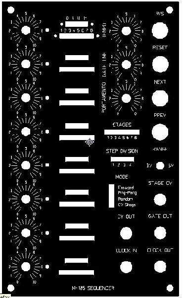
- on the stage gate switches, which end is P1/P5 (? the 2 or 3 pole end?)
- same as with the stage count, is P1 = step 8 or step 1?)
also i do not understand the wiring of step 2-8. do i need to connect each P2-P8 together (e.g. like a bus system?)
(and P1-p4 of the stage gate mode ?)
_________________
Homepage - http://www.czmok.de
My dIY - http://diy.czmok.de
Film/Music - http://gfm.me |
|
|
Back to top
|
|
|
ryktnk
Joined: Apr 24, 2008
Posts: 285
Location: london
Audio files: 1
|
| Posted: Sun Feb 15, 2009 1:35 pm Post subject:
|
|
|
| unit-sound wrote: | ryktnk:
i need some answers i finally got all parts for the frontpanel together and now i am working my way thru the diagrams and wiring out.
- on the stage gate switches, which end is P1/P5 (? the 2 or 3 pole end?)
- same as with the stage count, is P1 = step 8 or step 1?)
also i do not understand the wiring of step 2-8. do i need to connect each P2-P8 together (e.g. like a bus system?)
(and P1-p4 of the stage gate mode ?) |
hello
here are some answers !
stage mode switches [4way] - q1 [the pole] is the centre most pin on the row of three,
p1 is at one end p4 is at the other ! [makes no difference]
stage count switches [8way] - again the p1 or p8 you can chose
which end depending on orientation. q1 is the pin on its own.
there is a diagram of the switches posted previously on page8 of this thread
regarding the wiring, yes it is like a bus system where all the switches are wired in parallel, except the `q` poles of each switch.
hope this makes sense.
-ryk |
|
|
Back to top
|
|
|
janvanvolt
Joined: Nov 24, 2005
Posts: 285
Location: Mainz, Germany
|
| Posted: Sun Feb 15, 2009 4:15 pm Post subject:
|
|
|
| ryktnk wrote: | | unit-sound wrote: | ryktnk:
i need some answers i finally got all parts for the frontpanel together and now i am working my way thru the diagrams and wiring out.
- on the stage gate switches, which end is P1/P5 (? the 2 or 3 pole end?)
- same as with the stage count, is P1 = step 8 or step 1?)
also i do not understand the wiring of step 2-8. do i need to connect each P2-P8 together (e.g. like a bus system?)
(and P1-p4 of the stage gate mode ?) |
hello
here are some answers !
stage mode switches [4way] - q1 [the pole] is the centre most pin on the row of three,
p1 is at one end p4 is at the other ! [makes no difference]
stage count switches [8way] - again the p1 or p8 you can chose
which end depending on orientation. q1 is the pin on its own.
there is a diagram of the switches posted previously on page8 of this thread
regarding the wiring, yes it is like a bus system where all the switches are wired in parallel, except the `q` poles of each switch.
hope this makes sense.
-ryk |
okay, the Q1's are now clear i also measured it with the multimeter to be sure.
my question more or less regading P2 - P4 (and P2-P which part of P? is indicating the "lowest" position, e.g. P2 would be "I" and P3 = "II" and P4 ="l-" and as well P2-P8 = number 2-8 ? which part of P? is indicating the "lowest" position, e.g. P2 would be "I" and P3 = "II" and P4 ="l-" and as well P2-P8 = number 2-8 ?
(would seem logical to me).
if that's correct, i start bus'sing
_________________
Homepage - http://www.czmok.de
My dIY - http://diy.czmok.de
Film/Music - http://gfm.me |
|
|
Back to top
|
|
|
ryktnk
Joined: Apr 24, 2008
Posts: 285
Location: london
Audio files: 1
|
| Posted: Mon Feb 16, 2009 1:40 am Post subject:
|
|
|
| unit-sound wrote: |
okay, the Q1's are now clear i also measured it with the multimeter to be sure.
my question more or less regading P2 - P4 (and P2-P which part of P? is indicating the "lowest" position, e.g. P2 would be "I" and P3 = "II" and P4 ="l-" and as well P2-P8 = number 2-8 ?
(would seem logical to me).
if that's correct, i start bus'sing |
hello
yes you are correct.
-ryk |
|
|
Back to top
|
|
|
norman phay
Joined: Jun 29, 2007
Posts: 176
Location: North-East England
Audio files: 1
|
| Posted: Sun Feb 22, 2009 6:58 am Post subject:
|
|
|
Ryk, for the 547 transistors I have a bunch of mixed 547Bs and 547Cs. Does it matter which I use, and can I mix them on one board, please?
Many thanks. |
|
|
Back to top
|
|
|
ryktnk
Joined: Apr 24, 2008
Posts: 285
Location: london
Audio files: 1
|
| Posted: Mon Feb 23, 2009 2:58 am Post subject:
|
|
|
| Norman Phay wrote: | Ryk, for the 547 transistors I have a bunch of mixed 547Bs and 547Cs. Does it matter which I use, and can I mix them on one board, please?
Many thanks. |
Hello
They should be fine to use, perhaps use the same ones for the LED buffers
just so they are the same.
-ryk |
|
|
Back to top
|
|
|
lexvortex
Joined: May 14, 2008
Posts: 155
Location: Toronto
|
| Posted: Fri Mar 06, 2009 6:19 pm Post subject:
Screws for switches? |
|
|
Hi,
Where can I get the screws for the specialty switches from Ryktnk or what size I should look for? I've been to my local hardware and surplus store but can't get something to fit.
Thanks,
Dave |
|
|
Back to top
|
|
|
ryktnk
Joined: Apr 24, 2008
Posts: 285
Location: london
Audio files: 1
|
| Posted: Tue Mar 10, 2009 3:36 am Post subject:
Re: Screws for switches? |
|
|
| lexvortex wrote: | Hi,
Where can I get the screws for the specialty switches from Ryktnk or what size I should look for? I've been to my local hardware and surplus store but can't get something to fit.
Thanks,
Dave |
hello
sorry for the delay.
the screws for the switches I think are m2 thread, which is fairly small.
m3 is more common.
better to try and get them from electronic components
place such as Farnell or Rapid, as this size is probably to
small for DIY shop.
be aware of the depth of screw as well, as it shouldn't protrude
too much into the switch mechanism.
there are tech. drawings of the switches on page 8 of this thread.
-ryk |
|
|
Back to top
|
|
|
lexvortex
Joined: May 14, 2008
Posts: 155
Location: Toronto
|
|
|
Back to top
|
|
|
ryktnk
Joined: Apr 24, 2008
Posts: 285
Location: london
Audio files: 1
|
| Posted: Sat Mar 14, 2009 11:12 am Post subject:
|
|
|
| lexvortex wrote: | Hmmmm, I've looked at several sights for an M2.6 x 0.45 bolt size including the usual suspects (digi-key, etc) but can only find one type of bolt that will fit but its got a big ugly hex head likethis,
|
hello
try these guys:-
http://www.microfastenings.com/Home.aspx
they specialises in m2.6 and below.
-ryk |
|
|
Back to top
|
|
|
lexvortex
Joined: May 14, 2008
Posts: 155
Location: Toronto
|
| Posted: Sat Mar 14, 2009 4:32 pm Post subject:
|
|
|
Great!! Thanks, I just emailed them to get a quote
Cheers,
Dave |
|
|
Back to top
|
|
|
|

 Forum index » DIY Hardware and Software