| Author |
Message |
ryktnk

Joined: Apr 24, 2008
Posts: 285
Location: london
Audio files: 1
|
 Posted: Tue Mar 17, 2009 1:26 pm Post subject: Posted: Tue Mar 17, 2009 1:26 pm Post subject:
|
  |
|
Hello
I have been working on some modifications for the
M185 sequencer recently.
I have realised I don't use the CV stage control much, so
have made an alternate version of the software - V2.1.
This "mode 4" control is now a fixed length mode.
The sequence can be set to a fixed length [selectable in multiples of 2].
So even when you adjust individual stage lengths the sequence
length doesn't change.
This is great for dance music type stuff where you are syncing to
a drumbox and want the loop to repeat with the drumbox.
The spare input from the CV stage control can now be used [with
a little bit of modding and a CMOS 4066] as an output to control
the portamento, so you can program the note slide on or off
for each sequence stage.
PM me if you want the software update.
Also I will try and post the mod. schematics for the portamento control.
-ryk |
|
|
Back to top
|
|
 |
xpmtl

Joined: Aug 10, 2007
Posts: 162
Location: Brussels, Belgium
|
| Posted: Sun Mar 22, 2009 5:43 am Post subject:
|
|
|
ow, completly forgot to check this thread 
Do u have any pcb left? i'm interested by 2 pcbs with pics.
if they all gone can u add me on the waiting list.
Thanks
_________________
http://sdiy.xpmtl.net |
|
|
Back to top
|
|
|
ryktnk
Joined: Apr 24, 2008
Posts: 285
Location: london
Audio files: 1
|
| Posted: Sun Mar 22, 2009 12:53 pm Post subject:
|
|
|
| xpmtl wrote: | ow, completly forgot to check this thread
Do u have any pcb left? i'm interested by 2 pcbs with pics.
if they all gone can u add me on the waiting list.
Thanks |
Hello
Yes there are still some PCBs & PICs left if anyone is interested.
thanks
-ryk |
|
|
Back to top
|
|
|
ryktnk
Joined: Apr 24, 2008
Posts: 285
Location: london
Audio files: 1
|
| Posted: Sun Mar 22, 2009 12:57 pm Post subject:
|
|
|
Here are some details for the programmable portamento mod I have been
working on.
There are two options for this mod.
OPTION [1]
This requires the V2.1 software, and means you will relinquish the CV stage
control functionality, but you do get the new mode4 "fixed length sequence
mode" !
The portamento is set via programming each stage, using the "hold reset"
switch method described in the docs.
The settings are retained on power off.
OPTION [2]
This doesn't require new software, but you will need to add 8 1P2W switches
to the panel, and a bit more spaghetti wiring !
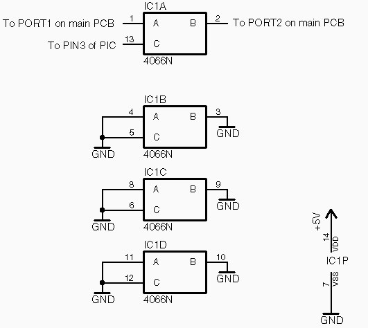
Option [1]
First of all if you have already built the PCB then remove the following
components:-
Q6, R13, R16. R19, R21
If you haven't built the PCB yet then do not include these components.
Then wire up a 4066 chip on a small piece of veroboard, using the
"Portamento mod opt 1" schematic diagram.
The mod board is connected to the main PCB via the GRND, +5, PORT1, PORT2
connectors, and PIN3 of the PIC chip.
Make sure the 4066 mod board is insulated and attach to the main PCB.
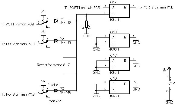
Option [2]
Wire up a 4066 chip on a small piece of veroboard, using the
"Portamento mod opt 2" schematic diagram.
You will need 8 1p2w toggle switches, 8 in4148 diodes, and a 1M resistor.
The switches are wired from the POT1 - POT8 connectors on the main PCB,
and to the mod board via the diodes.
The mod board is connected to the main PCB via the GRND, +5, PORT1, & PORT2
connectors.
Make sure the 4066 mod board is insulated and attach to the main PCB.
-ryk
| Description: |
|
| Filesize: |
27.98 KB |
| Viewed: |
13052 Time(s) |
|
| Description: |
|
| Filesize: |
49.42 KB |
| Viewed: |
412 Time(s) |
| This image has been reduced to fit the page. Click on it to enlarge. |
|
|
|
|
Back to top
|
|
|
lexvortex

Joined: May 14, 2008
Posts: 155
Location: Toronto
|
|
|
Back to top
|
|
|
janvanvolt

Joined: Nov 24, 2005
Posts: 285
Location: Mainz, Germany
|
| Posted: Mon Apr 20, 2009 4:47 am Post subject:
|
|
|
Hi Dave,
lucky you  i am still working on mine. Short question which you might be able to answer which is correct: i am still working on mine. Short question which you might be able to answer which is correct:
(a) wire up all P1-P8 1:1 and then add the resistors on P1
or
(b) add resistors on P1 and wire up P2-P8 and then connect it to the "resistor" points as well.
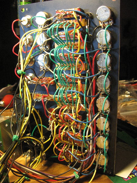
or even easier: show me the back of your frontpanel.
_________________
Homepage - http://www.czmok.de
My dIY - http://diy.czmok.de
Film/Music - http://gfm.me |
|
|
Back to top
|
|
|
lexvortex
Joined: May 14, 2008
Posts: 155
Location: Toronto
|
| Posted: Mon Apr 20, 2009 11:01 am Post subject:
|
|
|
Hi Unit-sound,
(a) is what I did, connect all the switches (1-8 ) in parallel and the resistors go on switch one only as shown on the diagram. I was initially confused at this too, actually at first I thought I was going to have to add resistors to all the switches  then I read though the construction guide and carefully followed the diagram and after a lot of wiring got through it then I read though the construction guide and carefully followed the diagram and after a lot of wiring got through it  although i think the portamento pot is shown wired backwards on the wiring diagram, it's an easy fix anyways if you have to fix it. although i think the portamento pot is shown wired backwards on the wiring diagram, it's an easy fix anyways if you have to fix it.
Cheers,
Dave |
|
|
Back to top
|
|
|
ryktnk
Joined: Apr 24, 2008
Posts: 285
Location: london
Audio files: 1
|
| Posted: Mon Apr 20, 2009 11:14 am Post subject:
|
|
|
Hello
Thanks Dave, that is correct.
Also your seq. looks great, congrats.
Sorry about the portamento pot error . . .
The wiring diagram is on page5 of this
thread if anyone else is puzzeld.
-ryk |
|
|
Back to top
|
|
|
numbernone
Joined: Aug 16, 2006
Posts: 477
Location: new york city
|
| Posted: Mon Apr 20, 2009 6:09 pm Post subject:
|
|
|
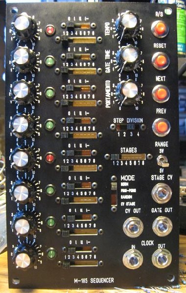
I would also love to see a shot of its backside, the front looks kickass! Real NASA vibe.
Also, where did you score your screws for the switches? Awesome look there as well. |
|
|
Back to top
|
|
|
lexvortex
Joined: May 14, 2008
Posts: 155
Location: Toronto
|
|
|
Back to top
|
|
|
numbernone
Joined: Aug 16, 2006
Posts: 477
Location: new york city
|
| Posted: Tue Apr 21, 2009 7:18 am Post subject:
|
|
|
WOW thanks Dave. Looks great, pretty much I what I had envisioned for the vertical columns of wiring. And double thanks for the link to the screws, I am very bad with such things.
Time to order my panels. |
|
|
Back to top
|
|
|
janvanvolt
Joined: Nov 24, 2005
Posts: 285
Location: Mainz, Germany
|
| Posted: Wed May 06, 2009 4:18 pm Post subject:
|
|
|
Panel wiring was really a mess doing it (and correcting errors) but ...
it sounds awesome it is really worth all the soldering and asssembling
_________________
Homepage - http://www.czmok.de
My dIY - http://diy.czmok.de
Film/Music - http://gfm.me |
|
|
Back to top
|
|
|
lexvortex
Joined: May 14, 2008
Posts: 155
Location: Toronto
|
| Posted: Wed May 06, 2009 9:22 pm Post subject:
Strange internal clock behaviour |
|
|
Hi,
I've finished the M-185 and it all seems to work great except for when I start the internal clock, the clock starts out fast then slows down and holds the tempo more or less form then on. What could cause this behaviour?
Thanks,
Dave |
|
|
Back to top
|
|
|
ryktnk
Joined: Apr 24, 2008
Posts: 285
Location: london
Audio files: 1
|
| Posted: Thu May 07, 2009 1:43 am Post subject:
Re: Strange internal clock behaviour |
|
|
| lexvortex wrote: | Hi,
I've finished the M-185 and it all seems to work great except for when I start the internal clock, the clock starts out fast then slows down and holds the tempo more or less form then on. What could cause this behaviour?
Thanks,
Dave |
Hello
mmm, sounds odd.
Maybe check the polarity of C1
Also try measuring if there is a voltage drop
or surge from the regulator IC5 before or after
the seq start.
Perhaps check the PCB wiring around the flip-flop IC3
make sure there is no short that could cause the S/S signal
to be grounded - ie wrong values for R35 R47 etc
Hope that helps
Let me know how you get on.
-ryk |
|
|
Back to top
|
|
|
lexvortex
Joined: May 14, 2008
Posts: 155
Location: Toronto
|
| Posted: Thu May 07, 2009 2:52 pm Post subject:
|
|
|
Hi Ryk,
I looked for wrong value resistors around IC 3 and they were all correct, I checked for a voltage drop or surge from IC 5 but the voltage was steady throughout. C1 is correct too.
When I first fired up the sequencer I had W3-W4 linked which made the internal clock not work at all. Could this have damaged something? I also do not have W2-W5 linked.
Thanks for the help ,
Dave |
|
|
Back to top
|
|
|
LektroiD

Joined: Aug 23, 2008
Posts: 1019
Location: Scottish Borders
Audio files: 2
G2 patch files: 2
|
| Posted: Thu May 07, 2009 8:16 pm Post subject:
|
|
|
Is there any chance we can get updated build docs for the 2.1 update (I bought mine with v2.1 PIC), I'm scanning up and down this thread getting mighty confused, I feel I'm going to make a mess of it all if I don't have it all concise and in one document.
I hope this is not too much hassle.
_________________
LektroiD |
|
|
Back to top
|
|
|
LektroiD
Joined: Aug 23, 2008
Posts: 1019
Location: Scottish Borders
Audio files: 2
G2 patch files: 2
|
| Posted: Thu May 07, 2009 8:16 pm Post subject:
|
|
|
Is there any chance we can get updated build docs for the 2.1 update (I bought mine with v2.1 PIC), I'm scanning up and down this thread getting mighty confused, I feel I'm going to make a mess of it all if I don't have it all concise and in one document.
I hope this is not too much hassle.
_________________
LektroiD |
|
|
Back to top
|
|
|
ryktnk
Joined: Apr 24, 2008
Posts: 285
Location: london
Audio files: 1
|
| Posted: Fri May 08, 2009 1:26 pm Post subject:
|
|
|
Hello
Sorry for the delay.
Here is the definitive documentation for the V2.1 version of this sequencer.
Please note these documents are only for use with V2.1 software, and are not an update on the existing documents.
Thanks
-ryk
| Description: |
|

Download (listen) |
| Filename: |
M185_V2.1_BOM.pdf |
| Filesize: |
58.95 KB |
| Downloaded: |
332 Time(s) |
| Description: |
|
Download (listen) |
| Filename: |
M185_V2.1_construction_notes.pdf |
| Filesize: |
352.4 KB |
| Downloaded: |
387 Time(s) |
| Description: |
|
Download (listen) |
| Filename: |
M185_V2.1_manual.pdf |
| Filesize: |
59.2 KB |
| Downloaded: |
425 Time(s) |
| Description: |
|
Download (listen) |
| Filename: |
M185_V2.1_panel_wiring.pdf |
| Filesize: |
330.59 KB |
| Downloaded: |
306 Time(s) |
|
|
|
Back to top
|
|
|
ryktnk
Joined: Apr 24, 2008
Posts: 285
Location: london
Audio files: 1
|
| Posted: Fri May 08, 2009 1:37 pm Post subject:
|
|
|
| lexvortex wrote: | Hi Ryk,
I looked for wrong value resistors around IC 3 and they were all correct, I checked for a voltage drop or surge from IC 5 but the voltage was steady throughout. C1 is correct too.
When I first fired up the sequencer I had W3-W4 linked which made the internal clock not work at all. Could this have damaged something? I also do not have W2-W5 linked.
Thanks for the help ,
Dave |
Hello
mmm.
The W3-W4 shouldn't have caused any damage, I think.
How quick is the "speed droop", over a second or longer ?
How fast is the start tempo before the droop, insanely faster, or just a little
bit faster ?
Is there any difference to the "speed droop" when the tempo control is
set to different positions ?
What brand and code is your IC2 ?
Thanks
-ryk |
|
|
Back to top
|
|
|
lexvortex
Joined: May 14, 2008
Posts: 155
Location: Toronto
|
| Posted: Fri May 08, 2009 3:35 pm Post subject:
|
|
|
Hi Ryk,
| Ryk wrote: | How quick is the "speed droop", over a second or longer ?
How fast is the start tempo before the droop, insanely faster, or just a little
bit faster ?
Is there any difference to the "speed droop" when the tempo control is
set to different positions ? |
The speed drop only lasts the first couple of stages and is only a little bit faster than the tempo, it happens for all tempos. And it happens only when I leave it on for a while without it running and then press Run. And the longer I let it sit the faster the initial speed before drooping. Weird 
| Ryk wrote: | | What brand and code is your IC2 ? |
The brand of IC 2 is "T" that's all that is on it then it M'SIA 9420W and on the second row it says TC4069UBP.
Thanks ,
Dave |
|
|
Back to top
|
|
|
funkyfarm

Joined: Jan 21, 2007
Posts: 583
Location: France
Audio files: 3
|
| Posted: Tue May 12, 2009 2:27 pm Post subject:
|
|
|
| ryktnk wrote: |
OPTION [1]
This requires the V2.1 software, and means you will relinquish the CV stage
control functionality, but you do get the new mode4 "fixed length sequence
mode" ! |
Hi !
I have the older firmware here and i guess i will not update it, and keep the CV stage control mode. ("relinguish" means you don't have it anymore, right ?)
Can we have a demo of the CV stage control functionality ?
The incoming cv voltage determines which of the eight steps is active ? range from 2.5 to 10 volts ? |
|
|
Back to top
|
|
|
ryktnk
Joined: Apr 24, 2008
Posts: 285
Location: london
Audio files: 1
|
| Posted: Tue May 12, 2009 3:17 pm Post subject:
|
|
|
| funkyfarm wrote: |
Hi !
I have the older firmware here and i guess i will not update it, and keep the CV stage control mode. ("relinguish" means you don't have it anymore, right ?)
Can we have a demo of the CV stage control functionality ?
The incoming cv voltage determines which of the eight steps is active ? range from 2.5 to 10 volts ? |
Hello
Yes if you want to use the V2.1 software you will lose the CV Stage
Control Function.
This CV Stage Control Function plays only the active stage selected by the Stage CV Input.
Stages 1 - 8 are selectable.
The voltage range can be adjusted from 0-10v, 0-5v, or 0-2.5v using
the RESET Extended Mode Function.
Please refer to the PDF manual on Page 6 of this thread
A demo might not be that exciting, as the stage that is playing will
just jump about depending on the CV Stage Input
So if a rising ramp LFO CV were used then the stages would play 1-8 and
then repeat from 1.
If a random voltage CV were used then the stages would play in random
order - although this function is already available with the RND play mode.
Hope that helps
-ryk |
|
|
Back to top
|
|
|
funkyfarm
Joined: Jan 21, 2007
Posts: 583
Location: France
Audio files: 3
|
| Posted: Thu May 14, 2009 1:57 pm Post subject:
|
|
|
Thank you for your answer, ryktnk
| ryktnk wrote: | | A demo might not be that exciting, as the stage that is playing will just jump about depending on the CV Stage Input |
I'm sure it could be pure fun with another sequencer as input, and i will wait for some 185 happy owner to put some blinking videos on youtube  |
|
|
Back to top
|
|
|
LektroiD
Joined: Aug 23, 2008
Posts: 1019
Location: Scottish Borders
Audio files: 2
G2 patch files: 2
|
| Posted: Thu May 21, 2009 2:55 am Post subject:
|
|
|
| funkyfarm wrote: | Thank you for your answer, ryktnk
| ryktnk wrote: | | A demo might not be that exciting, as the stage that is playing will just jump about depending on the CV Stage Input |
I'm sure it could be pure fun with another sequencer as input, and i will wait for some 185 happy owner to put some blinking videos on youtube |
Yes, I'd like to see a youtube of the v2.1 (still haven't got round to starting mine yet)
_________________
LektroiD |
|
|
Back to top
|
|
|
ryktnk
Joined: Apr 24, 2008
Posts: 285
Location: london
Audio files: 1
|
| Posted: Fri May 22, 2009 1:08 pm Post subject:
|
|
|
| LektroiD wrote: |
Yes, I'd like to see a youtube of the v2.1 (still haven't got round to starting mine yet) |
Hello
I'm still waiting for my panels for the V2.1 seq so no video yet.
But will try and post something soon . . . .
-ryk |
|
|
Back to top
|
|
|
|

 Forum index » DIY Hardware and Software