| Author |
Message |
dancelwerk
Joined: Aug 28, 2009
Posts: 93
Location: berlin
Audio files: 2
|
|
|
Back to top
|
|
 |
dancelwerk
Joined: Aug 28, 2009
Posts: 93
Location: berlin
Audio files: 2
|
 Posted: Sun Jan 10, 2010 10:50 am Post subject:
me again. Posted: Sun Jan 10, 2010 10:50 am Post subject:
me again. |
  |
|
hi again i can't wait to wiring, i finish again, and now this the initial report, i want to hear different notes when i move stage cv control pots
STAGE CV CONTROL POTS: doest not respond or yes i only can listen a tik, tik, tik
STAGE INDICATORS: works fine
STAGE GATE MODE CONTROL: works fine
STAGE COUNT CONTROL: works fine
TEMPO CONTROL: works fine, is a little fast in the minimun, i uses a 47K, not a 50K is it important?
GATE TIME CONTROL: i think is not working very well, works but i can't hear different note to check is like a closed envelope at minimum, tik, tik, tik
PORTAMENTO CONTROL: i think that is not working
STAGES CONTROL: perfect the leds makes the right job in the modes
RESET CONTROL
PREV CONTROL
NEXT CONTROL yes works fine
RANGE: i don't know very well, makes a change in the octave
STEPDIV CONTROL: i think working well
MODE CONTROL: yes working fine
CV OUT JACK: tik, tik, tik, i can hear any note, perhaps is not working
GATE OUT JACK: works fine
CLOCK IN JACK, works fine
CLOCK OUT JACK: i didn't check
ok i wait your answers again, perhaps the problem is on the pcb. |
|
|
Back to top
|
|
|
ryktnk

Joined: Apr 24, 2008
Posts: 285
Location: london
Audio files: 1
|
| Posted: Mon Jan 11, 2010 4:57 am Post subject:
Re: me again. |
|
|
| dancelwerk wrote: | hi again i can't wait to wiring, i finish again, and now this the initial report, i want to hear different notes when i move stage cv control pots
CV OUT JACK: tik, tik, tik, i can hear any note, perhaps is not working
. |
Hello
Sorry for the delay.
Sounds like the wiring for the switches is now ok [i couldn't see
any diff between opt A or opt B]
Make sure the other end of the 220k resistor is connected to ground.
What do you mean about
"CV OUT JACK: tik, tik, tik, i can hear any note, perhaps is not working
"
Have you connected this to an VCO, or are you just listening ?
Can you check the LED status.
If stop the clock, and then press RESET.
After RESET the first stage LED should light up, when you press UP
then it should light bright if the Gate Mode for the stage is set to an "ON" mode - ["I" "II" "-"] signalling there is a gate high.
You can also try DOWN to check the other stages of course.
If this is working then the Gate circuit is correct, and you can then
continue to test the CV circuit.
Use a multimeter to check the voltage on the POT
channel wire of the current stage that is active [Bright LED]
It should be about 5v.
Than check the wiper of that Potentiometer, if you turn
the dial it should swing from 0v to about 5v.
If this is ok, then check the voltage on the PCVS rail whilst adjusting the
potentiometer of the Lit stage.
This should go from 0v to about 5v.
If this is ok, then check the voltage on PORT1 [the wire to goes to the
portamento potentiometer]
This should also go form 0v to 5v when adjusting the CV potentiometer
of the lit stage.
If this is ok, then check the voltage on the PCV2, this is the wire that
goes to the voltage range switch.
This should also go form 0v to 5v when adjusting the CV potentiometer
of the lit stage.
Make sure the voltage range switch is correctly wired to PCV1, PCV2 and PCV3.
If all this works then hopefully there should be a healthy CV from
the CVOUT connection.
Let me know how you get on.
-ryk |
|
|
Back to top
|
|
|
dancelwerk
Joined: Aug 28, 2009
Posts: 93
Location: berlin
Audio files: 2
|
| Posted: Mon Jan 11, 2010 8:40 am Post subject:
Re: me again. |
|
|
[quote="ryktnk"] | dancelwerk wrote: |
Have you connected this to an VCO, or are you just listening
-ryk |
hahahaha, yes of course i have connected to a VCO, i try on Arp2600 (CV in) Korg Ms 20, (yes this is Hzvolt, but it should be works, am i wrong?), korg MS50 (+5-5 Volt IN) and Roland SH2, (CV and gate IN) but only get like a click, when i say Tik or click i refer to when you put all values of a ADSR to minimum you only hear a cutter sound that sounds like a "tik" ,
perhaps i am wrong connecting, i connect CVout of sequencer to CV in of synths and gate from GATEOUT of sequencer to CVgate in of Synths, Are the correct connections?
don't worry for the delay, i will check all that you said me and let you know.
Thanks for the support and sorry again.
Fernando |
|
|
Back to top
|
|
|
dancelwerk
Joined: Aug 28, 2009
Posts: 93
Location: berlin
Audio files: 2
|
| Posted: Mon Jan 11, 2010 11:50 am Post subject:
Re: me again. |
|
|
| ryktnk wrote: |
Can you check the LED status.
If stop the clock, and then press RESET.
After RESET the first stage LED should light up, when you press UP
then it should light bright if the Gate Mode for the stage is set to an "ON" mode - ["I" "II" "-"] signalling there is a gate high.
You can also try DOWN to check the other stages of course.
If this is working then the Gate circuit is correct, and you can then
continue to test the CV circuit.
-ryk |
ok it works fine
| ryktnk wrote: |
Use a multimeter to check the voltage on the POT
channel wire of the current stage that is active [Bright LED]
It should be about 5v.
Than check the wiper of that Potentiometer, if you turn
the dial it should swing from 0v to about 5v.
-ryk |
in the step 1 pot is about of 5V, always is continuous on 5v even when the sequencer is stop.
when i turn dial always 5V
and CVOUT in the pcb and for extension in the Jack socket always gives 14.14 V
is it normal???
-ryk[/quote] |
|
|
Back to top
|
|
|
dancelwerk
Joined: Aug 28, 2009
Posts: 93
Location: berlin
Audio files: 2
|
| Posted: Mon Jan 11, 2010 1:18 pm Post subject:
mp3 |
|
|
this is a sample start opening the gate time control from min to max and after rising up the tempo and down and closing the gate time control,
stages count are 8
stage gate mode control position 1
portamento at 0
stages control mode forward
Range 5v
stepdiv at 1
i hope you help to listen |
|
|
Back to top
|
|
|
dancelwerk
Joined: Aug 28, 2009
Posts: 93
Location: berlin
Audio files: 2
|
|
|
Back to top
|
|
|
dancelwerk
Joined: Aug 28, 2009
Posts: 93
Location: berlin
Audio files: 2
|
|
|
Back to top
|
|
|
ryktnk
Joined: Apr 24, 2008
Posts: 285
Location: london
Audio files: 1
|
| Posted: Wed Jan 13, 2010 1:41 am Post subject:
Re: me again. |
|
|
| dancelwerk wrote: |
in the step 1 pot is about of 5V, always is continuous on 5v even when the sequencer is stop.
when i turn dial always 5V
and CVOUT in the pcb and for extension in the Jack socket always gives 14.14 V
is it normal???
-ryk |
[/quote]
Hello
Are you checking the wiper voltage ?
If it is always 5V then you have wire the Potentiometer wrong.
You should be able to turn the Potentiometer and get 0V on the wiper,
as one side of the Potentiometer is connected to ground.
Have a look at the wiring on the Potentiometer.
-ryk |
|
|
Back to top
|
|
|
dancelwerk
Joined: Aug 28, 2009
Posts: 93
Location: berlin
Audio files: 2
|
| Posted: Wed Jan 13, 2010 8:54 am Post subject:
wiper is ok |
|
|
hi
wiper is ok check 0 at min and 5 at max
now what should i check? |
|
|
Back to top
|
|
|
dancelwerk
Joined: Aug 28, 2009
Posts: 93
Location: berlin
Audio files: 2
|
| Posted: Wed Jan 13, 2010 12:31 pm Post subject:
me again |
|
|
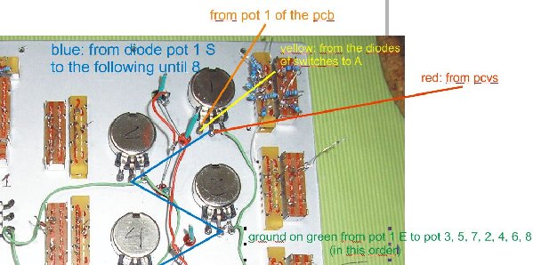
me again, lately this topic is monologue by me, sorry for the problems, but understand me,i want to the sequencer working, sorry again, i made another photomontage like i wired the potenciometers, perhaps i have an error, look at and say to me.
I try to help you to find a solution, thanks in advance.
Fernando.
| Description: |
|
| Filesize: |
121 KB |
| Viewed: |
290 Time(s) |
| This image has been reduced to fit the page. Click on it to enlarge. |
|
|
|
|
Back to top
|
|
|
ryktnk
Joined: Apr 24, 2008
Posts: 285
Location: london
Audio files: 1
|
| Posted: Thu Jan 14, 2010 5:00 am Post subject:
Re: wiper is ok |
|
|
| dancelwerk wrote: | hi
wiper is ok check 0 at min and 5 at max
now what should i check? |
Hello
If the wiper voltage swings in the range then follow the next steps
I wrote before:-
Check the voltage on the PCVS rail whilst adjusting the
potentiometer of the Lit stage.
This should go from 0v to about 5v.
If not then make sure all the diodes on the potentiometer wiper
connections are the correct way around.
If this is ok, then check the voltage on PORT1 [the wire to goes to the
portamento potentiometer]
This should also go form 0v to 5v when adjusting the CV potentiometer
of the lit stage.
If this is ok, then check the voltage on the PCV2, this is the wire that
goes to the voltage range switch.
This should also go form 0v to 5v when adjusting the CV potentiometer
of the lit stage.
Make sure the voltage range switch is correctly wired to PCV1, PCV2 and PCV3.
If all this works then hopefully there should be a healthy CV from
the CVOUT connection.
Let me know how you get on.
-ryk |
|
|
Back to top
|
|
|
dancelwerk
Joined: Aug 28, 2009
Posts: 93
Location: berlin
Audio files: 2
|
| Posted: Thu Jan 14, 2010 4:50 pm Post subject:
Re: wiper is ok |
|
|
| ryktnk wrote: | | dancelwerk wrote: | hi
wiper is ok check 0 at min and 5 at max
now what should i check? |
Hello
If the wiper voltage swings in the range then follow the next steps
I wrote before:-
Check the voltage on the PCVS rail whilst adjusting the
potentiometer of the Lit stage.
This should go from 0v to about 5v.
If not then make sure all the diodes on the potentiometer wiper
connections are the correct way around.
If this is ok, then check the voltage on PORT1 [the wire to goes to the
portamento potentiometer]
This should also go form 0v to 5v when adjusting the CV potentiometer
of the lit stage.
If this is ok, then check the voltage on the PCV2, this is the wire that
goes to the voltage range switch.
This should also go form 0v to 5v when adjusting the CV potentiometer
of the lit stage.
Make sure the voltage range switch is correctly wired to PCV1, PCV2 and PCV3.
If all this works then hopefully there should be a healthy CV from
the CVOUT connection.
Let me know how you get on.
-ryk |
all is ok, working, giving me the correct voltages you said, but didn't work, and I did try another thing, i unwired the cvout from pcb of the cvout jack (always give me the same value 2.2v), I wired a cable from pcvs rail from diodes directly to the cvout jack, and voila!, now i have control of the cv stages pots, i think the problem is from CVout circuit of the pcb,
what components do I check??
what do you think? |
|
|
Back to top
|
|
|
ryktnk
Joined: Apr 24, 2008
Posts: 285
Location: london
Audio files: 1
|
| Posted: Sat Jan 16, 2010 12:26 pm Post subject:
Re: wiper is ok |
|
|
| dancelwerk wrote: |
all is ok, working, giving me the correct voltages you said, but didn't work, and I did try another thing, i unwired the cvout from pcb of the cvout jack (always give me the same value 2.2v), I wired a cable from pcvs rail from diodes directly to the cvout jack, and voila!, now i have control of the cv stages pots, i think the problem is from CVout circuit of the pcb,
what components do I check??
what do you think? |
Hello
Ok.
If you have got the 0v-5v range on PCV2, then mos of the
CV circuit is working.
You should then check a few components -
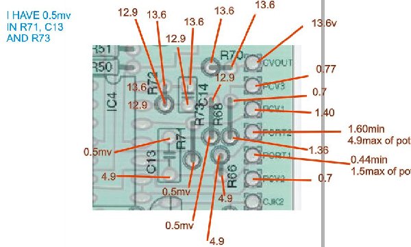
R68 - 66.6k
R71 - 100k
R73 - 100k
R72 - 5.26k
R70 - 560R
C14 - 220pF
This is the last stage part of the CV circuit
that scales the voltage with the range switch
for 0-3V and 0-5V.
It is based around 1C4D, so you should check carefully
the soldering of the pins of IC4, especially pins 12,13,14.
-ryk |
|
|
Back to top
|
|
|
dancelwerk
Joined: Aug 28, 2009
Posts: 93
Location: berlin
Audio files: 2
|
|
|
Back to top
|
|
|
ryktnk
Joined: Apr 24, 2008
Posts: 285
Location: london
Audio files: 1
|
| Posted: Tue Jan 19, 2010 3:25 am Post subject:
|
|
|
Hello
At what setting is the Stage CV pot when you took
these values, and was the Gate High [Bright LED] at the time ?
-ryk |
|
|
Back to top
|
|
|
dancelwerk
Joined: Aug 28, 2009
Posts: 93
Location: berlin
Audio files: 2
|
| Posted: Wed Jan 20, 2010 12:34 am Post subject:
hi again |
|
|
| i take this values with all stages cv at maximun in all gate high, stage at 8 steps switch at 3v |
|
|
Back to top
|
|
|
ryktnk
Joined: Apr 24, 2008
Posts: 285
Location: london
Audio files: 1
|
| Posted: Wed Jan 20, 2010 3:20 am Post subject:
Re: hi again |
|
|
| dancelwerk wrote: | | i take this values with all stages cv at maximun in all gate high, stage at 8 steps switch at 3v |
Hello
Well you should have nearly 5V on PORT1.
I thought you had agreed to this before ?
You need to make sure you have a Gate High output
for the S+H part of the CV circuit.
Make sure you have 5V on Pin 2 of IC1 - this will confirm you have
Gate High signal.
If this is true, and your PCVS is about 5V then there is something
wrong with the S+H part of the CV circuit.
Check the following components carefully.
R59 - 10M
R66 - 1M
R43 - 100k
R49 - 47k
R36 - 10k
R37 - 22k
R44 - 22k
R50 - 100k
R51 - 22k
D5 - check polarity
Q15 - 2N3819
Q11 - BC547
Q10 - BC558
If PCVS is around 5V you should also have about 5V on Pin 1 of IC4.
-ryk |
|
|
Back to top
|
|
|
dancelwerk
Joined: Aug 28, 2009
Posts: 93
Location: berlin
Audio files: 2
|
| Posted: Thu Jan 21, 2010 12:52 am Post subject:
no 5v in port1 |
|
|
hi Ryk,
i haven't 5V on Port1 and i haven't 5V in the pin 2 of Ic1. |
|
|
Back to top
|
|
|
ryktnk
Joined: Apr 24, 2008
Posts: 285
Location: london
Audio files: 1
|
| Posted: Thu Jan 21, 2010 1:31 am Post subject:
Re: no 5v in port1 |
|
|
| dancelwerk wrote: | hi Ryk,
i haven't 5V on Port1 and i haven't 5V in the pin 2 of Ic1. |
Hello
Sorry, previously on the "Thu Jan 14, 2010 11:50 pm" Post, you said that you did have this voltage on Port1.
Ok, if you don't have 5V on pin2 of IC1, then you don't have a Gate High
output.
You can only do all the voltage checks I described previously
when the gate output is High [5v on pin2 IC1]
This means you haven't followed the steps I mentioned
about using the Reset button and then the UP or Down button
to select a stage with a High Gate mode [gate mode I,II, or I-].
Please do this first, and then start to perform the voltage checks
previously.
Are ALL your Stage Gate Mode switches wired correctly ?
If not then you will not get a Gate High output.
This is really important, as the CV only gets routed through to
the CV Out when their is a Gate High output, this probably explains
why the Pots are having no effect.
-ryk |
|
|
Back to top
|
|
|
dancelwerk
Joined: Aug 28, 2009
Posts: 93
Location: berlin
Audio files: 2
|
| Posted: Thu Jan 21, 2010 10:15 am Post subject:
power supply |
|
|
hi again ryk, after all I find the main problem, the power supply, -15v wire cable was broken, now i get better values, sorry, sorry, sorry, I am shamed,

I was going you crazy, sorry again, I recheck again well all values and i reported problems if there is.
thanks to be patient with me.

Fernando. |
|
|
Back to top
|
|
|
ryktnk
Joined: Apr 24, 2008
Posts: 285
Location: london
Audio files: 1
|
| Posted: Fri Jan 22, 2010 3:52 am Post subject:
Re: power supply |
|
|
| dancelwerk wrote: | hi again ryk, after all I find the main problem, the power supply, -15v wire cable was broken, now i get better values, sorry, sorry, sorry, I am shamed,
I was going you crazy, sorry again, I recheck again well all values and i reported problems if there is.
thanks to be patient with me.
Fernando. |
Hello
No problem.
Glad you found the problem.
-ryk |
|
|
Back to top
|
|
|
julian

Joined: Jan 11, 2008
Posts: 103
Location: UK
|
| Posted: Sun Jan 31, 2010 12:06 pm Post subject:
|
|
|
Just a quick note - ive allready posted this to the trade section, but the content is quite relevant to this thread....
http://www.thebeast.co.uk/cnc/sale.html
If you click on the link, you will find a selection of panels, in different formats, and for different devices, and a handfull for the m185. Some are perfect whilst others have defects that have caused me not to sepperate them from usual stock.
All panels are photographed, and any defects noted. Some panels are very cheap, whilst others are just good value.
Im located in the UK (europe). The company runs accounts in both euro and sterling, and can take cards with all the usual caveats.
I will ship internationally at cost price. Indication of postal costs are given.
In an ideal world, i wont be making b-grade duplicates.... ; ) So hopefully, when theyre gone, thats it at the given price.
Thank you,
Julian
_________________
For custom cnc engraved panels see - http://www.thebeast.co.uk/cnc/
|
|
|
Back to top
|
|
|
Danno Gee Ray
Joined: Sep 25, 2005
Posts: 1351
Location: Telford, PA USA
|
| Posted: Sat Mar 20, 2010 4:25 pm Post subject:
|
|
|
| Anyone know a Mouser or Digikey part number for 3.5mm Cliff Jacks? |
|
|
Back to top
|
|
|
emdot_ambient
Joined: Nov 22, 2009
Posts: 667
Location: Frederick, MD
|
| Posted: Sat Mar 27, 2010 8:18 pm Post subject:
|
|
|
| ryktnk wrote: | Here are some details for the programmable portamento mod...There are two options for this mod.
OPTION [1]
This requires the V2.1 software...The portamento is set via programming each stage, using the "hold reset" switch method described in the docs.
OPTION [2]
This doesn't require new software, but you will need to add 8 1P2W switches to the panel, and a bit more spaghetti wiring |
Clarification: If you have V2.1 can you only use Option 1? From reading the docs Option 1 doesn't sound as functional in a live situation as Option 2.
Oh, and my boards/PIC arrived last week  |
|
|
Back to top
|
|
|
|

 Forum index » DIY Hardware and Software