| Author |
Message |
State Machine
Janitor


Joined: Apr 17, 2006
Posts: 2810
Location: New York
Audio files: 24
|
 Posted: Tue Aug 12, 2008 12:43 pm Post subject: Posted: Tue Aug 12, 2008 12:43 pm Post subject:
|
  |
|
| Quote: | | I imagine if you laid the softpot on Plexiglass with LEDs underneath, it would show through. It'd probably look pretty cool, I imagine |
Yes, Indeed 
| Quote: | | Mainly the debouncing/edge detector. I think the comparator is solid enough to do its thing without that |
At the very least, maybe using a comparator with a 1.5 M resistor strapped in to out for hysterisis just as was done with the Klee 2 input conditioning?
I plan to re-read Ian's retrigger ideas myself.
As far as another road trip ,oh no not again .... !!! Just when your on a roll. Can you take your lab bench with you? 
PS: If anyone has not seen Ian's website, please go there. There is some brilliant stuff in those pages .... Some of the more unusual type projects I think. You might want to put you math hat on for some of hte talks though Ian has posted his site earlier in this thread ......
Great guys, this is a very cool thread !!!!! A good perspective of the design process and the trading off that goes on..
Bill |
|
|
Back to top
|
|
 |
Scott Stites
Janitor

Joined: Dec 23, 2005
Posts: 4127
Location: Mount Hope, KS USA
Audio files: 96
|
| Posted: Tue Aug 12, 2008 1:00 pm Post subject:
|
|
|
Where do you get them there math hats? 
I've got 2M2 hysterisis resistor, bipolar powered comparator through a diode to CMOS.
_________________
My Site |
|
|
Back to top
|
|
|
widdly
Joined: Jun 25, 2007
Posts: 268
Location: singapore
G2 patch files: 2
|
| Posted: Tue Aug 12, 2008 7:39 pm Post subject:
|
|
|
| Scott Stites wrote: |
The differential output is high on my list - seems I saw someone using a ribbon controller on a synth (maybe it was a CS80, dunno) that seemed to bend the notes the same, regardless of where the ribbon was touched. I'd find that immensely useful, myself, when using it as a modulation controller.
|
Korg prophecy log wheel has this. It's a fun controller.

Last edited by widdly on Thu Aug 05, 2010 10:09 pm; edited 1 time in total |
|
|
Back to top
|
|
|
Scott Stites
Janitor
Joined: Dec 23, 2005
Posts: 4127
Location: Mount Hope, KS USA
Audio files: 96
|
| Posted: Tue Aug 12, 2008 7:49 pm Post subject:
|
|
|
| Quote: | | Korg prophecy log wheel has this. It's a fun controller. |
Ahr har!
I got the differential output working! With it, pressing anywhere on the ribbon controller will provide 0V on the output, and if one moves the appendage up past the original point of pressure, the voltage rises and if one moves the appendage down past the original point of pressure, the voltage drops. This works great for moving a keyboard voltage up and down - finger roll vibrato or rapid or slow zings up or down (or both).
This is a fairly simple implementation right now - when the appendage is lifted, the voltage drops back to zero. So, if you bend a keyboard note up or down, then release the appendage, the note drops back to the original value. It's very smooth. One has to be careful not to apply too much pressure when first pressing the ribbon, as pressure will bend the note right away.
This voltage is available simultaneously with the normal output voltage. I had a lot of fun doing this:
I tried controlling a VCO with the keyboard and the differential output, and and controlling the filter with the normal output. By tapping up and down the ribbon, I could play out a tune with the filter cutoff while holding the note. I could pause at any point in the filter sweep generated by the ribbon cable and wiggle VCO tone up and down. Also, I could sweep the VCO up and down simultaneously with the filter, with different starting points of the filter - it just depended on where I initially touched the ribbon cable. With my appendage.
I can see where an inverted copy of the differential voltage would be handy.
It warn't as easy to do as I intended - I had to wait for around four samples of S&H 3 before I could sample it with the reference S&H used for the differential output and get a relieable zero reading. In operation, it's seamless, though. The zero point is driftless when no appendage is applied, because when the appendage is lifted, the reference sample and hold tracks sample and hold 3, and they cancel each other out.
Cheerios,
Scott
_________________
My Site |
|
|
Back to top
|
|
|
Scott Stites
Janitor
Joined: Dec 23, 2005
Posts: 4127
Location: Mount Hope, KS USA
Audio files: 96
|
| Posted: Wed Aug 13, 2008 7:09 am Post subject:
|
|
|
The differential voltage works so well, I think it would be possible to incorporate a quantizer, yet maintain analog glide. My initial objection to quantization was that I didn't want any steppiness in glides, etc. However, using the differential voltage, the initial note could be quantized and the differential voltage could be summed with the quanitzed voltage to produce analog slides, etc.
At the appendage up position, the DAC would grab that value and hold it. It would have to be a fairly high resolution DAC to snag the appendage up voltage without some apparent shift in voltage (pitch if its controlling a VCO).
All that's down the road. I want to finish the basic stuff first. Re-triggering is what I'll look at next, but probably not until the weekend.
I'd also like to have a basic design posted if people want to use that without all the jewjaws before I get into all that. In fact, quantization with scales and all that good stuff would be best under FPGA or PIC control, which is not my field of knowledge at all. Maybe a board that takes the basic analog voltage and timing info from this one and does all the cool scaling, etc. would be the ticket. Some sort of State Machine. Maybe the boards could be called "The Finger" and "The Digit". 
_________________
My Site |
|
|
Back to top
|
|
|
frijitz
Joined: May 04, 2007
Posts: 1734
Location: NM USA
Audio files: 54
|
| Posted: Wed Aug 13, 2008 7:47 am Post subject:
|
|
|
| Scott Stites wrote: | | I got the differential output working! With it, pressing anywhere on the ribbon controller will provide 0V on the output, and if one moves the appendage up past the original point of pressure, the voltage rises and if one moves the appendage down past the original point of pressure, the voltage drops. This works great for moving a keyboard voltage up and down - finger roll vibrato or rapid or slow zings up or down (or both). |
Scott --
Nice! I'm glad to see you are trying out your ideas as you go along, rather than just thinking about them. Very important for alternate controller work.
Re the retriggering idea -- since this will require a separate circuit, you might as well use the signal as a separate output (rather than switching between the two). That way you can trigger one kind of event when the first appendage hits and another kind when the second one hits.
Ian |
|
|
Back to top
|
|
|
Scott Stites
Janitor
Joined: Dec 23, 2005
Posts: 4127
Location: Mount Hope, KS USA
Audio files: 96
|
| Posted: Wed Aug 13, 2008 10:24 am Post subject:
|
|
|
Thanks Ian, that's a pretty good idea! Now if I can get my head around these differentiators.
I guess deriving the re-triggers is going to be a balance between how much voltage movement will be required vs how fast it's moving. The voltage to excite the re-trigger will have to be moving faster than the fastest appendage can slide up or down the ribbon (a point above a fast slide so that hammer-ons can be detected accurately). Yet, a hammer-on voltage interval of (at minimum) a half step would desirably be enough to do it.
_________________
My Site |
|
|
Back to top
|
|
|
Scott Stites
Janitor
Joined: Dec 23, 2005
Posts: 4127
Location: Mount Hope, KS USA
Audio files: 96
|
| Posted: Wed Aug 13, 2008 11:43 am Post subject:
|
|
|
I was just thinking that a cool thing to do would be to provide an output/function that held the initial note only, which could be bent around with the differential voltage.
Then it occurred to me - I already did!
The "reference" sample and hold, which is differentially summed with the position sample and hold (S&H3) is already holding that information. All I would have to do is mix the differential voltage with that output and...bam!
One app that applies right away (along with the obvious pitch bend) is to be able to hammer a note, then slide the filter around that. Or, one could connect the differential output to a vca, hit a note, then control the volume of the note by sliding the appendage up the ribbon. A special version of the differential voltage where negative excursions get inverted to positive would allow one to even fade in the highest notes by sliding down.
_________________
My Site |
|
|
Back to top
|
|
|
frijitz
Joined: May 04, 2007
Posts: 1734
Location: NM USA
Audio files: 54
|
| Posted: Wed Aug 13, 2008 11:45 am Post subject:
|
|
|
| Scott Stites wrote: | Now if I can get my head around these differentiators.
I guess deriving the re-triggers is going to be a balance between how much voltage movement will be required vs how fast it's moving. The voltage to excite the re-trigger will have to be moving faster than the fastest appendage can slide up or down the ribbon (a point above a fast slide so that hammer-ons can be detected accurately). Yet, a hammer-on voltage interval of (at minimum) a half step would desirably be enough to do it. |
Right. There is an implicit assumption that your playing style will be (or become) compatible with what the circuit can do. You will use your deliberate free will to operate the controller, i.e., you will hammer crisply and at a finite interval when you want a trigger and you will not try to glide too fast when you do not want a trigger. If you go outside of certain bounds you may be able to defeat the circuit. But you can also make traditional instruments squeak and skronk and break up if you play them wrong.
Always remember that the most expressive controllers (violin, say) are the hardest to learn to play, the hardest to control. So don't be worried if you have to practice on this one a bit as well as adjust it critically.
Then again, the whole idea may never work at all for you.
You will probably need to make the differentiator bipolar. For mine, I have a high speed differentiator followed by a unity gain inverter, with steering diodes to detect the more negative signal. This fires a 555 one-shot. You might want to include a pot for sensitivity control, especially during your initial trials.
Good luck!
Ian |
|
|
Back to top
|
|
|
Scott Stites
Janitor
Joined: Dec 23, 2005
Posts: 4127
Location: Mount Hope, KS USA
Audio files: 96
|
| Posted: Wed Aug 13, 2008 11:24 pm Post subject:
|
|
|
| Quote: | | Right. There is an implicit assumption that your playing style will be (or become) compatible with what the circuit can do. You will use your deliberate free will to operate the controller, i.e., you will hammer crisply and at a finite interval when you want a trigger and you will not try to glide too fast when you do not want a trigger. If you go outside of certain bounds you may be able to defeat the circuit. But you can also make traditional instruments squeak and skronk and break up if you play them wrong. |
All of that is so true. And, the more I explore this thing, the more I find aspects of it that are certainly like a unique instrument. In fact, there are so many directions to go when one starts to think of all the potential control configurations.
| Quote: | | Always remember that the most expressive controllers (violin, say) are the hardest to learn to play, the hardest to control. So don't be worried if you have to practice on this one a bit as well as adjust it critically. |
I think it will ultimately have some qualities about it that will require a certain amount of technique.
| Quote: | | Then again, the whole idea may never work at all for you. |
As I look into it, I find that it becomes more useful with each turn of the circuit. Tonight, even though it's a floppy ribbon lying on the bench, I had a configuration of it that seemed very natural right off the bat to play. It was getting pretty ethereal with very little effort.
It's related to the function I mentioned earlier - grabbing the first note value that it sees and holding that. I used the fourth sample and hold, which is used to also generate the differential voltage. Last night, I had a simple setup triggering the differential voltage - it would bend positive and negative, relative to the pressure point on the ribbon. When it was released, it would fall back to zero - like a spring loaded pitch bend, I suppose.
I had the idea today that - hey - that S&H is still putting out a voltage, why not also use that? It worked pretty well, actually. It was a simple matter to put in a switch/circuitry that would change the differential sample and hold from returning to zero (IE, the same potential as the third sample and hold) and just stay where it was once the appendage was removed from the ribbon. This has the effect of leaving the differential voltage at the last point it was at before pressure was released - an option I was after to begin with, but it also makes the voltage out of the differential sample and hold unique - it stays where it's at once you press the ribbon. Once you press the ribbon cable again, it then samples that voltage.
The "normal" ribbon voltage does that, but, unlike that voltage, if you slide up and down before removing pressure, this voltage doesn't move. In fact, it's initially more accurate than the normal CV, because now you don't stand the chance of bending the note with too much pressure when you intially press the ribbon. It's exactly like tapping on a keyboard with infinite resolution.
Now, the really cool part kicks in: I had the "normal" ribbon voltage controlling the filter cutoff, and I had the differential voltage controlling a VCA which had an LFO passing through it,which I used to modulate the VCO. This new "hold" voltage was controlling the V/Oct input of the VCO. Initally, pressing the ribbon locked the note in. The more "up" I slid my appendage, the brighter the note got AND it gradually introduced a perfectly controllable vibrato. In fact, I could, easily sweep the vibrato in and out - from nothing to full on crazy modulation. If I moved down past the initial point of contact, the vibrato died away, and the note grew darker. The effect was profound - I've never had the feeling of having such fine control over my synth before. If I intially closed the filter all the way down, and set a longish attack on the EG, the effect was really something as I hit a note, then glided up and down. One appendage control over several parameters at the same time - pitch, filter cutoff, modulation, gating - each reacting in a different, yet controllable manner.
I should have made a sample, but I figured I better get to work and document the breadboard, which I still hadn't started yet. That ended up taking a while (and I've only done the differential CV portion). I write it down, draw it on computer, fix the mistakes, do it again 'til everything agrees. I don't want to start over should I change something and "can't get back".
| Quote: | | You will probably need to make the differentiator bipolar. For mine, I have a high speed differentiator followed by a unity gain inverter, with steering diodes to detect the more negative signal. This fires a 555 one-shot. You might want to include a pot for sensitivity control, especially during your initial trials. |
Thanks for that! That let's me know how to go about it.
Cheers,
Scott
_________________
My Site |
|
|
Back to top
|
|
|
Scott Stites
Janitor
Joined: Dec 23, 2005
Posts: 4127
Location: Mount Hope, KS USA
Audio files: 96
|
| Posted: Fri Aug 15, 2008 7:19 am Post subject:
|
|
|
There are a number of opportunities to make this thing a really versatile instrument. Hopefully it can provide a lot of versatility, yet remain fairly easy to set up and use.
The greatest power, of course, is that it provides a simple control surface with which to generate and control output voltages and synchronization. Right now, the number of unique unique simultaneous control voltages it produces is nine (not counting some inversions or signal input mode). Differential voltage really let the cat out of the bag - six of the control voltage responses were derived from that function.
Right now I'll try to describe the three main generated voltages from which all the others are derived:
1. Continuous Positional Output Voltage. While moving up or down the ribbon, the voltage tracks the position. When pressure is released, the voltage retains the last positional voltage that was generated before pressure is released.
2. Fixed Positional Voltage (CV2). Each time pressure is applied, the initial positional voltage is sampled and held. While retaining pressure on the ribbon and moving the appendage up or down on the ribbon, this voltage does not change. Its action on release depends on if "hold" or "normal" is selcted. If "normal", the fixed positional voltage will go to the last positional voltage sampled by CV1 before pressure is released. If "hold" is selected, the voltage will remain unchanged until the next pressure is applied, whereupon it will sample that initial value, and the process repeats. Mixing differential voltage with this voltage will provide a means of sliding or vibrato.
3. Continuous Differential Voltage (Diff CV). When the ribbon is first pressed, this output is at zero volts. When the appendage slides "above" the original point of contact, while pressure is applied, the differential voltage will rise (positive) relative to the original position. When the appendage slides "below" the original point of contact, the voltage will fall negative, relative to the original position. For pressure release, like CV2, its behavior depends on if the "Hold" or "Normal" mode is in effect. In normal mode, the voltage will return instantly to zero (if it's at some non-zero value) when pressure is released. In hold mode, it will lock to the current value when pressure is released. In that case, when the next pressure event starts, it will return to zero volts, and the process will repeat.
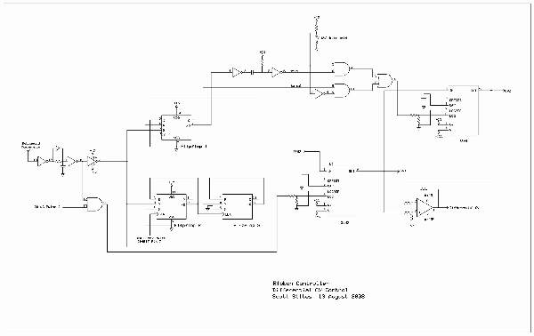
I've uploaded a block-like schematic of what I have working so far (it all works as of this writing).
All three voltages are derived from manipulation of two different Sample and Hold's - S&H3 and S&H4 (S&H1 and S&H2 are part of the analog shift register responsible for grabbing stable voltages for S&H3).
Starting with note off - the comparator is low. Flipflop 1 Set input is high, so Flipflop 1 Q output is high.
If the CV2/Diff Hold switch is closed, this high signal is transferred straight to the S&H4 clock input, which allows it to track its signal input, which is fed from the output of S&H3. The output of S&H3 and S&H4 are therefore at the same potential, so there is 0V differential - the Differential CV is 0V. CV1 and CV2 are at the same potential as well - which would be the last voltage sampled by S&H3.
If the CV2/Diff Hold switch is open, the clock input of S&H4 is low, so it is holding the last sample it took - which was the voltage initially loaded into S&H3 at the initial press of the ribbon the last time it was pressed. The differential voltage will be the value of S&H3 voltage plus or minus S&H4 voltage.
In this state, the reset pin of Flipflops 2 and 3 are held high, which holds their Q outputs low, and /Q outputs high. Because they are held in reset mode, they ignore the clock pulses coming from the third output of the CD4017, which is used to sequentially clock the first three S&H's.
When the ribbon is pressed (note on) Set goes low on Flipflop 1. The Q output does not go low yet - it's waiting to be reset by Flipflop 3.
At the same time, Reset on flipflops 2 and 3 also goes low. This allows Flipflop 2 to be clocked by the third sequential clock pulse from the CD4017. These two flipflops form a divide by four counter. This is intended to give S&H3 plenty of time to acquire a stable voltage before its output is sampled by S&H4 (by plenty of time, I don't intend to imply observeable latency - there is no apparent latency).
At the rising edge of the fourth clock pulse, Q of Flipflop 3 goes high. This resets Flipflop 1, which brings its Q output low and its /Q output high. When /Q goes high, this initiates a pulse that is blocked by the switch's action on the AND gate feeding the summing OR gate on the input of the S&H4 pulse input.
If the CV2/Diff Hold switch is closed, S&H4 been constantly tracking S&H3 already. When Flipflop 1 Q goes low, this locks the current voltage on the ouput of S&H3 into S&H4. The voltage on CV2 is now fixed at this same voltage (because CV2 always reflects the contents of S&H4). As the appendage is dragged up and down the ribbon, S&H3 voltage varies and so does the differential CV output, because its output is added and subtracted with the fixed output of S&H4.
If the CV2/Diff Hold switch is open, S&H4 been holding the initial voltage value recorded when the ribbon was first pressed on the previous note - it hasn't been tracking S&H3. When Flipflop 1 /Q goes low, this creates a sample pulse that "locks" the current voltage on the ouput of S&H3 into S&H4, creating a new initial note voltage. CV2 puts out this same voltage now. As the appendage is dragged up and down the ribbon, S&H3 voltage varies and so does the differential CV output, because its added and subtracted with the fixed output of S&H4. The voltage on CV2, which is S&H4s output voltage, remains fixed at the initial voltage of S&H3 when the pressure was first sensed on the ribbon.
Once again pressure is released. If the switch is closed, S&H4 locks the last value of S&H3 onto its output. This causes the differential to snap back to 0V (if it was at some other value) and causes CV4 to snap to the last positional voltage recorded by S&H3.
When pressure is released and the switch is open, S&H4 does not take another sample of S&H3 and remains fixed at its current voltage, which was the initial note voltage recorded when the ribbon was pressed. The differential output stays at whatever value it was at when the ribbon was released - it will only return to 0 at the start of the next note.
Cheerios,
Scott
| Description: |
| CV1, CV2 and Differential Control |
|
| Filesize: |
82.27 KB |
| Viewed: |
392 Time(s) |
| This image has been reduced to fit the page. Click on it to enlarge. |
|
_________________
My Site |
|
|
Back to top
|
|
|
Scott Stites
Janitor
Joined: Dec 23, 2005
Posts: 4127
Location: Mount Hope, KS USA
Audio files: 96
|
| Posted: Fri Aug 15, 2008 8:42 am Post subject:
|
|
|
Here's a diagram of the six control voltage permutations I mentioned in the previous post.
The bottom of each graph illustrates that the initial point of contact is always 0V. This can be anywhere on the ribbon controller, not just the center. The horizontal line at the bottom shows the direction of movement on the ribbon cable while applying pressure after the initial contact. The graph above shows the direction of travel and polarity of voltage on each CV output as the appendage slides up and down on the controller from the initial contact point.
This is not just kitchen sinking for kitchen sinking's sake - I've tried these out, and they can have some very profound uses. Take number 5 for example: say you are using CV2 (fixed initial note, no slide) and you're using a slide control out to control filter cutoff. If you hit a note at the upper end of the ribbon, you don't have any more room to slide up. However, you've got plenty of room to slide down, which will also open the filter just as sliding up from the initial point of contact will do (and sliding back up to intial will close it back down). In fact, playing this really opened my eyes to how musical opening a filter on oscillator slides going up and going down is. I used the continuous output to slide a VCO, and the number 5 output to control the filter cutoff. The initial note is darker - as the note slides up, it gets brighter (as is normal). Sliding back down also opened up the filter for some gnarly bass.
This arrangement is also very, very good for smaller ribbon cables that would be used as controllers (like a pitch or modulation wheel). In that case, you could view it as sort of a one axis JAG.
Cheerios,
Scott
| Description: |
| Differential CV Permutations |
|
| Filesize: |
12.25 KB |
| Viewed: |
263 Time(s) |
| This image has been reduced to fit the page. Click on it to enlarge. |

|
_________________
My Site |
|
|
Back to top
|
|
|
fonik

Joined: Jun 07, 2006
Posts: 3950
Location: Germany
Audio files: 23
|
| Posted: Fri Aug 15, 2008 10:31 am Post subject:
|
|
|
this is very exciting, scott. great, great, great. i jst printed out your last two posts and will read them carefully.
first the klee and now this controller! thank you, scott for sharing.
_________________

cheers,
matthias
____________
Big Boss at fonitronik
Tech Buddy at Random*Source |
|
|
Back to top
|
|
|
Scott Stites
Janitor
Joined: Dec 23, 2005
Posts: 4127
Location: Mount Hope, KS USA
Audio files: 96
|
| Posted: Fri Aug 15, 2008 12:05 pm Post subject:
|
|
|
I'm pretty excited about it, Fonik! Actually, if everything works out to how I'm envisioning it, it'll be a nice mate for the Klee. The Klee will be able to feed it control voltages and triggers, and the ribbon cable will be able to feed the Klee the same. I think it would make for some pretty cool interaction with the Klee.
Hey Ian: The idea for retriggering with a differentiator is looking like it's going to work just fine. I plan on feeding the differentiator with permuation 6 on my differential permutation chart - that way if a step is of a particular interval up or down, the waveform seen by the differentiator will be the same.
I'm shooting for an interval of, at minimum, a half step (83 mV) to excite the retrigger.
I think I might get away without using a lag. The target voltage here won't move nearly as quickly as the breath controller would at the point the re-trigger would be used. I set up a differentiator with a gain of 3.3.
Sending a negative going 83 mV pulse to it generates a positive spike of around 140 mV. If I feed it a negative going 7V triangle wave at ~4 Hz, the differentiator output stays below 100 mV. I figure a triangle wave at 4 Hz would be like sweeping up and down the entire ribbon four times a second at a very high range setting, so hammer-ons of a halfstep or so in either direction ought to retrigger while slides are ignored.
Once I confirm that all the above does actually work, the next trick will be defeating the re-trigger on (non-trilled) note-on and note-off events. I think I can solve that with some timing signals and CMOS logic.
Cheerios,
Scott
_________________
My Site |
|
|
Back to top
|
|
|
frijitz
Joined: May 04, 2007
Posts: 1734
Location: NM USA
Audio files: 54
|
| Posted: Fri Aug 15, 2008 9:45 pm Post subject:
|
|
|
| Scott Stites wrote: | | The idea for retriggering with a differentiator is looking like it's going to work just fine. I plan on feeding the differentiator with permuation 6 on my differential permutation chart - that way if a step is of a particular interval up or down, the waveform seen by the differentiator will be the same. |
Oh yeah, you already have the bipolar part built in.
| Quote: | | I'm shooting for an interval of, at minimum, a half step (83 mV) to excite the retrigger. |
Sensible place to start, at least.
| Quote: | | I think I might get away without using a lag. The target voltage here won't move nearly as quickly as the breath controller would at the point the re-trigger would be used. |
I was also wondering -- would there be a way to just use the (finite) difference between two of the S/H outputs instead of making a differentiator circuit? I guess you would be back to needing to make it bipolar.
| Quote: | | I set up a differentiator with a gain of 3.3. Sending a negative going 83 mV pulse to it generates a positive spike of around 140 mV. If I feed it a negative going 7V triangle wave at ~4 Hz, the differentiator output stays below 100 mV. I figure a triangle wave at 4 Hz would be like sweeping up and down the entire ribbon four times a second at a very high range setting, so hammer-ons of a halfstep or so in either direction ought to retrigger while slides are ignored. |
Ah, good. I had kinda a gut feeling that the slides and hammers wouldn't be too hard to discriminate.
| Quote: | | Once I confirm that all the above does actually work, the next trick will be defeating the re-trigger on (non-trilled) note-on and note-off events. I think I can solve that with some timing signals and CMOS logic. |
Mmmmmm ... You might want to leave in the note-ons. Think if you were using only the retrigger line feding an AD generator. You would probably want those OAD (one appendage down) events to be there. Did I just make it trickier?
At what point do you decide to just do all this with a PIC? After all, you'll eventually want a MIDI stream, right? 
Ian |
|
|
Back to top
|
|
|
Scott Stites
Janitor
Joined: Dec 23, 2005
Posts: 4127
Location: Mount Hope, KS USA
Audio files: 96
|
| Posted: Fri Aug 15, 2008 10:34 pm Post subject:
|
|
|
Hey Ian,
| Quote: | | I was also wondering -- would there be a way to just use the (finite) difference between two of the S/H outputs instead of making a differentiator circuit? I guess you would be back to needing to make it bipolar. |
Oh, now you mention it...
Well, thinking about it, that would work initially. One S&H is fixed at note on, and the other moves. However, once you slid (without removing the appendage), wouldn't that move one S&H out of range of trilling after the slide? I gotta think about that more.
| Quote: | | Quote: | | I set up a differentiator with a gain of 3.3. Sending a negative going 83 mV pulse to it generates a positive spike of around 140 mV. If I feed it a negative going 7V triangle wave at ~4 Hz, the differentiator output stays below 100 mV. I figure a triangle wave at 4 Hz would be like sweeping up and down the entire ribbon four times a second at a very high range setting, so hammer-ons of a halfstep or so in either direction ought to retrigger while slides are ignored. |
Ah, good. I had kinda a gut feeling that the slides and hammers wouldn't be too hard to discriminate. |
Real life was a bit different on how things turned out - I think I got pretty close to half step range of trills. Sliding very quickly will produce an extra trigger. But, you were right about the nature of it - the "blat" works in very well with a very fast slide. It's easy enough to avoid, too, through technique.
| Quote: | | Quote: | | Once I confirm that all the above does actually work, the next trick will be defeating the re-trigger on (non-trilled) note-on and note-off events. I think I can solve that with some timing signals and CMOS logic. |
Mmmmmm ... You might want to leave in the note-ons. Think if you were using only the retrigger line feding an AD generator. You would probably want those OAD (one appendage down) events to be there. Did I just make it trickier? |
Yes, you're very right about that. Actually, I initially excluded the original note from retriggering - it would only re-trigger on the upper note (if trilling up) or the lower note (when trilling down). This was due to the nature of the original circuit, though, I hadn't stepped in to intercede.
I went with the original plan (the ideal diode section steering all voltages from the differential amplifier negative). This produced positive pulses with each change, and I ran those through a comparator. Actually, just the one trigger on the upper or lower trilled note is a neat effect. But, I knew that, neat as it was, it would still be nice to trigger on both notes. It took me long enough to realize all I had to do was set up a comparator to trigger on the negative excursions from the differentiator and OR the two comparator outputs together. That worked very well.
| Quote: | | At what point do you decide to just do all this with a PIC? After all, you'll eventually want a MIDI stream, right? |
Gasp!
I'm not ready for that yet. I am super-chuffed. This thing is really coming together now - the re-triggering option really adds *a lot*. This thing feels very natural to play, even though it's still flopping around on my bench - I can't imagine what it will be like when it's mounted solid.
The differential permutations serve a real purpose - I'm finding that positional control of things like filter cutoff, amplitude, etc. sinks in and becomes second nature really quickly. Forming these voltages from the differential output is a surprisingly expressive method of producing differing voltages along one axis. For example, how far the filter opens depends on where the slide starts and how far it extends. With a "dark" filtered note, one can slide the filter all the way open, release, then play the same note again with the filter shut down. The permutations determine what happens if it's an up slide or a down slide (or either). Right now I'm using permutation 5 to control cutoff, so I can open up the bass with a slide down or open up the treble with a slide up.
I'm wondering about slide velocity voltage now......
But first, I need to reorganize the breadboard and toss the bits I'm not using. It's getting kind of furry. I've also got to burn some samples of this thing. My studio/shop is so torn apart from working on it, I'll have to reorganize/tidy up to get the recorder going again.
I've decided to name it "The Appendage". Who's idea was that? I'll have to read back through the thread.
Cheers,
Scott
_________________
My Site |
|
|
Back to top
|
|
|
State Machine
Janitor
Joined: Apr 17, 2006
Posts: 2810
Location: New York
Audio files: 24
|
| Posted: Sat Aug 16, 2008 7:48 am Post subject:
|
|
|
Oh dear, I have to catch up here .......... Scott, absolutely fantastic stuff here. Ian, great dialog as well and contributions .......... OK, I can say anything intelligent until I read more here ............. I can say this, the amount of control will be astounding
Reading more here .............. and, wow, I can't believe it Scott, your allowed to stay up that late .......... geez .......
Oh, hey Fonik !!!!!!!!!
Bill |
|
|
Back to top
|
|
|
State Machine
Janitor
Joined: Apr 17, 2006
Posts: 2810
Location: New York
Audio files: 24
|
| Posted: Sat Aug 16, 2008 7:51 am Post subject:
|
|
|
| Quote: | | 've decided to name it "The Appendage". Who's idea was that? I'll have to read back through the thread. |
or ............... "The Finger" ............. I kind of like that ..... sort of "punk rockish" to me
Bill |
|
|
Back to top
|
|
|
Coriolis

Joined: Apr 11, 2005
Posts: 616
Location: Stilling, Denmark
|
| Posted: Sat Aug 16, 2008 8:33 am Post subject:
|
|
|
Will there be a lot of talking here in the future of "Giving Klee the Finger"? 
C
_________________
Some Rubber Stamp Sound Effects - and other sound effects |
|
|
Back to top
|
|
|
Scott Stites
Janitor
Joined: Dec 23, 2005
Posts: 4127
Location: Mount Hope, KS USA
Audio files: 96
|
| Posted: Sat Aug 16, 2008 11:48 pm Post subject:
|
|
|
I figured I'd leave the name "The Finger" for Eric Barbour to use.
I recorded a couple of quick samples tonight. Bear in mind (again) that this ribbon is just flopping loose, so playing it is like trying to hit a moving target. I basically have to try to hold it by the edge while molesting it. About 1/4 of the left side (low notes) is hanging up in the air attached to the breadboard, so it's unplayable. Basically I'm just pecking around on it.
Anyway, the samples demonstrate a few different things - retriggering on hammer-ons, modulation by sliding, and the difference between CV1 and CV2.
Each sample uses the same patch (I recorded the two sequentially). The patch is two VCOs through the 2040 filter through a VCA, with a little reverb. The trigger out and gate out are connected to an ADSR envelope generator. The envelope generator is providing the envelope for the VCA and the filter. The differential output, in Mode 5, is also controlling the filter cutoff. This CV works by starting at 0 wherever the ribbon is pressed. Then, while pressing the ribbon controller, moving right or moving left from that point will increase the CV in a positive direction. The Appendage is in CV hold mode, so when the pressure is released, the differential output stays at the voltage it was at until the next pressure is applied, whereupon it returns to zero and uses the new initial position on the ribbon as its zero point.
I have the EG set with a rather pointed attack/decay, with a low sustain to demonstrate the retriggering.
appendage_cv1_retrigger.mp3: CV1 will always glide in pitch as the ribbon is pressed and the pressure slides up and down the ribbon. Because the Appendage is in hold mode, when pressure is released, the pitch stays where it's at until the next pressure point is applied, whereupon the pitch goes to the new contact point's position. As pressure is kept on the ribbon, moving up and down causes the filter to open up - it closes when it passes the original pressure point. Releasing the pressure then re-applying it starts the filter at the original level. That's why some notes are more subdued and others are brighter - it's very easy to control at will.
Re-triggering applies to hammer-ons. While pressure is applied, hammering on a different point (up or down) will cause a trigger to fire (past a certain interval) on the hammered note - this is re-trigger pulse 1. When the hammer-on note is released, a second trigger fires - this is re-trigger pulse 2. Both of these triggers can be made available as separate outputs to control external events. In this patch, they're mixed with the initial note-on trigger.
appendage_cv2_retriggin.mp3: CV2 does not naturally glide. It grabs the initial voltage value wherever the ribbon is pressed and holds that note. Sliding while pressure applied still applies the modulation. All of the filter sweeps heard in this sample are simply me sliding up and/or down on the ribbon while keeping pressure applied. Releasing and applying pressure again sets the voltage to zero wherever the ribbon is pressed, and that is the new "reference point" for the CV. It starts off with the same voice as the CV1 sample. After a little while, I increase the resonance of the filter so the sweeps can be more clearly heard.
Before the two minute mark, the Appendage is re-triggering like it was in the CV1 sample. Now hammering on triggers the same note, but with different filter cutoffs. At the two minute mark or so there is a pause as I disconnect from the combined trigger output and go to just the intial note-on trigger only. At the end of the sample, you can hear the difference in how the filter hammer-ons work.
BTW, CV2 can be made to slide simply by mixing in either CV1 or one of the differential voltages. This same voltage used to modulate the filter could be used to bend the note up as one rolls the finger to the left or the right - it's actually a very sweet sounding vibrato. I didn't have it in this sample though...
Cheerios,
Scott
| Description: |
| Appendage CV2 Output - Retriggered the single trigger |
|

Download (listen) |
| Filename: |
appendage_cv2_triggin.mp3 |
| Filesize: |
4.98 MB |
| Downloaded: |
1224 Time(s) |
| Description: |
|
Download (listen) |
| Filename: |
appendage_cv1_retrigger.mp3 |
| Filesize: |
3.48 MB |
| Downloaded: |
1166 Time(s) |
_________________
My Site |
|
|
Back to top
|
|
|
Coriolis
Joined: Apr 11, 2005
Posts: 616
Location: Stilling, Denmark
|
|
|
Back to top
|
|
|
Scott Stites
Janitor
Joined: Dec 23, 2005
Posts: 4127
Location: Mount Hope, KS USA
Audio files: 96
|
| Posted: Sun Aug 17, 2008 8:05 am Post subject:
|
|
|
If one were to set up a selector switch to a mix input from any of the differential permutations, that would allow one to set the response of CV2 to any slide response one wanted for that CV.
1. Normal: Fixed initial, no slide
2. Slide 1: Left slides down, right slides up
3. Slide 2: Left stays fixed, right slides up
4. Slide 3: Left slides down, right stays fixed
5. Slide 4: Left slides up, right stays fixed
6. Slide 5: Left stays fixed, right slides down
7. Slide 6: Left Slides up, right slides up
8. Slide 7: Left slides down, right slides down
Then, of course, one could invert the selection. This would bring in the "left slides up, right slides down".
Taking it a step further, one could provide a selector switch for CV1 that did sort of the same thing, though CV1 slides naturally. By sort of, I mean the responses would be different yet again (because of summation and subtraction).
Going in the same order, the permutations would have this effect:
1. Left slides down, right slides up (normal).
2. Left slides down at twice the rate and right slides up at twice the rate.
3. Left slides down at normal rate, right slides up at twice the rate.
4. Left slides down at twice the rate, right slides up at normal rate.
5. Left stays fixed and right slides up at normal rate.
6. Left slides down at normal rate, right stays fixed.
7. Left stays fixed and right slides up at twice the rate.
8. Left slides down at twice the rate, right stays fixed.
This could be inverted as well. In that case, inverting the response of the permutation as it's mixed in would cause number 2 to create no slide at all.
Reason I mention this is I've got a cool patch running that has a high oscillator controlled by CV1 and a low oscillator controlled by CV2, only CV2 now slides up left or right. The interplay is cool.
This stuff could go on forever, you realize......
_________________
My Site |
|
|
Back to top
|
|
|
State Machine
Janitor
Joined: Apr 17, 2006
Posts: 2810
Location: New York
Audio files: 24
|
| Posted: Sun Aug 17, 2008 8:25 am Post subject:
|
|
|
Scott, the results are amazing. Great expression for a ribbon just hanging in the breeze !!! Just imagine when it's actually mounted to a flat surface. Great research and development ....
| Quote: | | This stuff could go on forever, you realize...... |
Oh yes, when to put that period at the end of any research is a hard decision to make !! The core features you developed thus far are keepers it seems to me.
Bill |
|
|
Back to top
|
|
|
Scott Stites
Janitor
Joined: Dec 23, 2005
Posts: 4127
Location: Mount Hope, KS USA
Audio files: 96
|
| Posted: Sun Aug 17, 2008 12:46 pm Post subject:
|
|
|
Well, certainly I'm going to try inserting a DAC. Main thing is the DAC will need to be high resolution but inexpensive and not unobtainium (I'm considering stacking two DAC08s and choosing the resolution from the 16 bits supplied).
This would eliminate the analog shift register, though I'd still need to maintain two S&Hs for the CV outputs. They would need only be simple S&Hs - as long as they don't have any significant lag in the ms or less range. The DAC would also tighten up timing; the analog shift register is a hedged bet that the ribbon voltage has been acquired.
However, the DAC is primarily for infinite hold, but I'm willing to put in defeatable 0.083V/step (half step musical interval) quantization on the outputs as well. Slide would still be possible via analog means, so it wouldn't be steppy. Just the initial note value would be quantized.
The nature of the design will preserve the availability of the control, gate, and trigger outputs (all of the features) discussed here.
The main challenge for me was a way to acquire voltages and hold them in "memory", with the parts available to me, while at the same time generating gate and trigger signals (my original intent did not include re-triggering, but Ian showed me the light on why that would be a good thing). Now that I have an idea of the timing, I think a DAC will eventually take over a bit of the work load (I'm thinking I might be able to use it to discern re-triggering as well). A good basic core design will be nice for those who want a simple frikkin' modwheel-scale controller, thank you very much, which is something I'd also like to have. The core will be expandable to the big Kahuna, which I also have every intention of building. The differential voltage perms are a very powerful thing, even for a small modwheel style controller.
But first, I need to firm up/simplify/document this design. DAC probably won't happen 'til after Malaysia.
Cheers,
Scott
_________________
My Site |
|
|
Back to top
|
|
|
Scott Stites
Janitor
Joined: Dec 23, 2005
Posts: 4127
Location: Mount Hope, KS USA
Audio files: 96
|
| Posted: Tue Aug 19, 2008 11:39 am Post subject:
|
|
|
I took a break from the Appendage BB on Sunday, for the most part. Yesterday I moved the main gate/trigger stimulus to the output of the divide by four counter. I noticed that synchronization with differential and its permutations would cause a 'knock' on the first new note if there was a wide gap (when using differential CV to modulate something). That's now fixed.
I recorded most of the breadboard circuitry yesterday, with the exception of the trigger generators and differentiator values. I need to re-organize the breadboard - it's crowded with a lot of unused stuff. I killed a CD40106 yesterday because of that, so I'm documenting it as it is now.
Having said that, the schematic is really not all that complicated. There are a few things I want to try to enhance it a bit more.
One of the things that makes it rather difficult to use yet for some aspects of pitch control is that the pressure (area of finger) laid on it will cause the pitch to shift. For pressure-related vibrato, that's pretty nice. For trying to end a held note at a specific pitch, it can be a bitch - it very easily can drop as the finger is removed. Part of it is due to technique - how one removes the finger, for example, but I think it could be made easier. Tapping the finger for short staccato notes doesn't incur this particular wrath, BTW. CV2 is immune as well, as it grabs only the initial pitch value (unless, of course, it's mixed with differential voltage to provide a slide).
The softpot is very sensitive, and there's a fine line between enough pressure and no pressure. It's fairly difficult to unflatten the finger enough to get the desired ending pitch without inadvertently triggering another note. What I plan to do is create a release time on the order of milliseconds - if when releasing the pressure, there are brief openings and closures, it will not produce a gate/trigger event, but instead just update the sample and hold. After a certain amount of time expires (unnoticeable during normal play), then it will accept a new note. This (I think) will make it easier to gradually withdraw pressure (unflatten the finger) to end with the desired pitch during slide play.
It would be very easy to add a "hold" switch - a momentary switch that ensures the pitch you're at will not deviate, no matter how you remove the finger. That breaks my philosphy of having this a one appendage device, but, at the same time, would be a very simple thing to operate.
I have another line of attack planned as well - this will serve to make pitch deviation on release an easier thing for fast, heavy play. As mentioned before, mixing differential voltage with CV2 causes a very nice, controllable slide. CV2 itself is fixed at the initial value when pressure is applied - the differential voltage slides it up and down past this point. The idea is to be able to modify the differential voltage to have a certain space between upward and downward movement where the voltage doesn't move at all. This would have the effect of placing the finger on the ribbon, then having a "null" spot of variable width. This null spot would be at the initial note value. Sliding up past the right side of the null would raise the pitch, sliding down past the left hand side of the null would lower the pitch. This would keep pressure deviation from happening at the initial note value (though that would go away once one slid past the null). Better still, though, it could provide a nice, more easily nailable point to slide to. Say you enter a note, slide up, then want to slide back to that original note. This would make that very easy to do.
On the kitchen sink front, I think it would be entirely possible to turn the single axis ribbon output to a dual axis output. Left finger would provide an output and right finger would provide a separate output. Sort of like a two axis joystick split out on a single axis. But, that comes later (it will require a bit of re-tooling of this idea, which I want to thoroughly wring out first).
Cheerios,
Scott
_________________
My Site |
|
|
Back to top
|
|
|
|

 Forum index » DIY Hardware and Software

